
In general, the German Navy used stereoscopic rangefinders during both World Wars. These had a "mark" which had to be centered on the midships-area of the target. During this same period, the British were using co-incident rangefinders which produced two pictures of the target, which then had to be merged together in order to produce a uniform picture. The British system was (once the range was found) of deadly precision, but better for short ranges than for long ones. The British sometimes got into trouble with their rangefinders, especially in conditions of poor visibility (for example, at the Battle of Jutland). The German stereoscopic system was remarkably good at finding the initial range, but it needed operators with special aptitudes reinforced with constant training for them to keep track of the target during a battle. Unknown to the British, stereoscopic systems also have an advantage in that they cannot be "spoofed" by changing the profiles of the target, which meant that the British wasted a great deal of effort during WWI by adding various extra details to their ships with that intent.
Prior to World War I, it was known that the human eye can measure angles to a minimum error of 10 angular seconds. This is the smallest angle that one can recognize between an object and a certain measuring mark by using special instruments. The effect of this minimum eye-error in terms of measuring distance with a range finder can be calculated with respect to the base-length of the rangefinder. For a rangefinder with a base length of 3 m and a twenty-fifth fold magnification, at 20 hm the error would be +/- 2.6 m, at 100 hm the error would be 65 m and at 160 hm it would be 165 m. This error is linear, that is, if you double the base-length of the rangefinder, then the fault distance is reduced by half.
Zeiss Optical Company was the primary developer of German rangefinders, and attempted from the beginning to deliver the highest possible precision. In spite of their best efforts, they found that they were unable to prevent their rangefinders from giving poor results. The primary causes of these problems were determined to be from the following sources: The permanent rhythmic oscillation found on ships created by the propulsion machinery, mainly the gearsets; the comparatively rough usage; and from the single-side heating of the optical elements making up the rangefinder from the effects of the sun, funnel smoke and engine exhaust air. Solutions were developed during the war to add "internal correction" and by 1918 these fixes were assembled to all ship-mounted rangefinders. The main adjustment was to add a special internal mirror system whereby the light going from one eyepiece was sent to the other eyepiece. Using the range decimation marks, the rangefinder was adjusted until both eyepieces were at infinite range. However, although workable, this system was not really satisfactory.
Following World War I, the errors in measuring were classified in three groups:
- Errors by the appurtenances
- Errors by the atmospherical environment
- Errors by the Operator
By increasing the base of rangefinders (formerly 3 and 6 m) up to 4, 5, 6, 7, and 10 m, the range of measurement and accuracy was greatly improved. Also very useful was an optical innovation called "bluecoating". This was a patented coat which was sputtered on all of the lenses and mirrors surface, making the image brighter and clearer. To minimize the atmospherical errors the whole rangefinder was temperature isolated, the used glass was insensitive to temperature while in addition airdryers and ventilating blowers were built in the tubes. The blowers were also assembled together with rotating clear-view screens to the optical parts of the telescope sights. The main innovation was a mechanism called "Umschlag" (officially called: R.U.Em.). It was this a system to make a quick calibration of the rangefinder simply by turning a certain leverarm. This affected a turnover of the whole optic inside the basetube. Before doing this, the operator has to adjust the optics to infinite range, turn over and look again. If the adjustment is still showing infinite range, then the rangefinder was calibrated. If not, the operator adjusted again, turned back - and so on. This system was first built in on SCHLESIEN and EMDEN in 1926. During the tests it turns out that also the form, color and brightness of the measuring lines and marks had its influence on the performance of the rangefinder operator. Later the marks could be highlighted or darkened and together with colored, exchangeable glasses so the optics could customized for the certain target and its environment. To relieve the load on the rangefinder operator, he was supported by a second man who cared for the correct train and by a third man for the correct elevation for AA rangefinding. In the early 30' also the main psychological influences were determined. Rangefinder operators were only selected after a special, very hard and difficult test and they need to prove their performance almost every day. They were given permanent psychological support and the training was very intensive. Onboard almost every ship were so-called P.A.G.'s (Prüf- und Ausbildungsgerät) for the training. The personnel were asked to deliver only "honest" ranges. The spotters often turned their marks away from the target and then closed in again. When they were sure of the range, they pushed a trigger which sent the range to the "determine-party" where the incoming ranges were graphically displayed and entered a range-solution to the analog fire control computer. Later this instrument was improved to serve also as a range and deflection plotter.
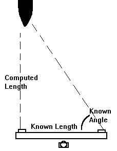
This appendix shows how to calculate the error in an optical rangefinder per the article above. Please keep in mind that the "range triangle" for these rangefinders is always a right-angle one with the bottom of the triangle being the rangefinder's baselength and the top being the target. Please see the Addendum below for further information.
Using Peter's first example of a 3 m rangefinder giving 2.6 m of error at 2,000 m, the following is an exercise showing how this error is calculated.
As given in Peter's essay, the range to the target is 20 hm, which is 2,000 m.
Since the rangefinder is specified as 25X, this means that, to the RF operator, the apparent range is 2,000 / 25 = 80 m. However, for these calculations it is easier to use the magnification factor as increasing the base-length of the rangefinder rather than as decreasing the range. So, we will use a perceived base length of 3 m X 25 or 75 m in these calculations.
Also, rather than work in seconds and minutes, let's work in pure angles (it's much easier on the calculator - meaning me). There are 3,600 seconds of arc in one degree. So:
Think of the rangefinder's base-length as being the bottom of a right-angle
triangle, with the top of the triangle being the target. The hypotenuse
side of a right-angle triangle is determined by the well-known formula:
The sine of bottom angle for this triangle is equal to:
So, arc-sine for this value gives us an angle of 87.8524158 degrees.
Adding to this angle our uncertainty factor of 0.002777778 degrees gives us an angle of 87.85519235 degrees.
The tangent of this angle is 26.70123547
This times the base-length of 75 m = 2,002.59266 m
Which is an error of about 2.6 m, just as Peter says above.
This error determination can be simplified into the formula below:
To take another example, the US Battleships of the North Carolina, South
Dakota and Iowa classes had main director rangefinders of 25X power with
a base length of 26 feet 6 inches (8.0772 m). For the same 2,000
m distance used above:
Continuing with the other ranges used by Peter; at 100 hm the error would be 24 m and at 160 hm the error would be 62 m. So, in line with Peter's comment above, increasing the base length by 2.7 times results in reducing the error by about 60%.
Some of you may be wondering why these calculations are done out to so many decimal points. The reason is that even large changes in range will change the rangefinder angle by only a very tiny amount. Taking our example of the US Battleship rangefinder with its baselength of 8.0772 m; as calculated above, the angle for a target at a range of 20,000 m is 89.97686 degrees. For a 21,000 m range, the angle is 89.97796 degrees. So, for a 5% change in range, the rangefinder angle changes by only 0.00110 degrees, or just a smidgen over one one-thousandth of a degree. As I said earlier, fractions are important.
In the time since I originally did this appendix some months ago, I received a note questioning my calculations. In figuring out where the gentleman had gone wrong, I found that he was unaware of a basic design principle behind most optical rangefinders, to wit: Only one end of the optical system changes angles, not both. The other end is always fixed at a right angle. This means that the "range triangle," as discussed above, is always a right-angle scalene triangle (no two sides the same length), it is not, as the gentleman supposed, an isosceles one (two sides the same length).
The reason for this is somewhat obvious, once you think about it. If both ends of the optical system move, then they must be kept absolutely, perfectly synchronized with each other down to the smallest fraction, something very hard to do on a stationary platform, let alone on a moving warship. If they are not kept synchronized down to the last decimal place, then that would mean that each one would be at a different angle when viewing a target. This would obviously make it impossible to correctly compute the range to the target. Again, as shown in the appendix above, a tiny error will make a large change in the range solution. Making one end of the range finder a fixed angle thereby removes a problem source.
I make a point of this as it is one of those things that I normally think "everybody knows that" and so do not usually believe that it is necessary to include such basic information in these essays. However, as this gentleman's note pointed out to me, not everyone does know these kinds of things and it was an error on my part to make such an assumption.
In case you are curious, it is usually the left end of the range finder that is fixed while the right end moves. This is because this design means that the focus adjusting knob is conveniently located for a right-handed operator.
16 July 2001 - Benchmark
19 December 2001 - Updated "Appendix: An Exercise in Trigonometry."
24 September 2004 - Updated "Appendix: How Rangefinders Work."
27 June 2019 - Updated to HTML 5 format, added range errors for US battleship rangefinder