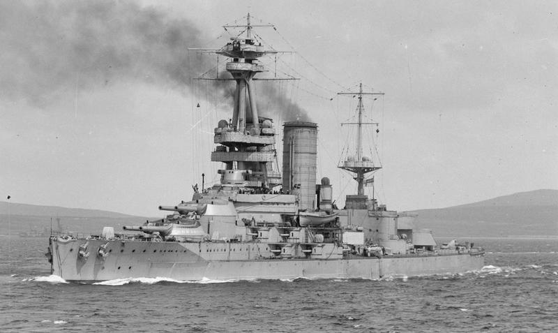
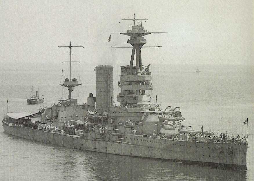
The Chilean government had two battleships building in British yards at the start of World War I, Almirante Latorre and Almirante Cochrane, both armed with Elswick weapons. These ships were taken over by the British in 1915, with Almirante Latorre being completed as the battleship HMS Canada and Almirante Cochrane completed as the aircraft carrier HMS Eagle. At the end of the war, HMS Canada was sold back to Chile, once again named Almirante Cochrane, and served in the Chilean Navy until stricken in 1958.
The Mark I was an Elswick design of wire-wound construction with an Elswick three-motion short-arm breech mechanism utilizing a Welin breech plug. The breech was power operated with a manual back-up. Fourteen guns were produced with the four reserve guns, which were never used, differing in having a sharper taper on the inner A tube. The DNO considered that the inner A tube of these original guns to be too thick and the later guns were built to a lighter design. The spare guns were scrapped in 1922.
Ten additional guns were ordered for Almirante Cochrane and three of these were completed with railway mountings but never used in France. The railway guns had the forward slope of their chambers reduced from 1 in 8 to 1 in 15 in order to prevent the shell from slipping back at high elevations.
The Mark III was the designation given to two guns built by Elswick for the Japanese battleship Yamashiro but not delivered. They are thought to have been the same as other 14-inch (35.6 cm) guns built for the Japanese Navy. These two guns were altered to give a ballistic performance identical to the Mark I. Compared to the Mark I, the main constructional differences were that they were about 1.5 tons (1.6 mt) lighter, had Vickers breech mechanisms, the inner A tube had forward shoulders with cannelured rings - to reduce "steel choke" - and were not tapered. These Mark III guns were not used afloat but were used on railway mountings in France.
The muzzle velocity and shell weight of the 14" (35.6 cm) Mark I did not differ appreciatively from that of the 14" (35.6 cm) Mark VII carried by the King George V class battleships of World War II. If anything, the older guns had slightly better performance considering that they fired shells of poorer aerodynamic qualities than did the newer guns (4crh vs. 6crh).
The data that follows is specifically for the Mark I guns used on HMS Canada although the Mark III should have had similar if not identical performance.
| Designation | 14"/45 (35.6 cm) Mark I
14"/45 (35.6 cm) Mark III |
|---|---|
| Ship Class Used On | Mark I: HMS Canada (ex-Almirante Latorre)
Mark III: Intended for IJN Yamashiro, but used as railway guns |
| Date Of Design | 1910 |
| Date In Service | 1915 |
| Gun Weight | 84.75 tons (86.11 mt) |
| Gun Length oa | 648.4 in (16.469 m) |
| Bore Length | 630 in (16.002 m) |
| Rifling Length | 529.8 in (13.457 m) |
| Grooves | (84) 0.12 in deep x 0.349 in (3.05 mm x 8.86 mm) |
| Lands | 0.174 in (4.42 mm) |
| Twist | Uniform RH 1 in 30 |
| Chamber Volume | 23,500 in3 (385.1 dm3) |
| Rate Of Fire | About 2 rounds per minute |
| Type | Bag |
|---|---|
| Projectile Types and Weights | APC Mark Ia - 1,586 lbs. (719 kg)
APC Mark IIIa (Greenboy) - 1,595 lbs. (723.5 kg) CPC - 1,586 lbs. (719 kg) HE - 1,586 lbs. (719 kg) |
| Bursting Charge | APC Mark Ia - 61.4 lbs. (27.9 kg)
APC Mark IIIa - 37.5 lbs. (17.0 kg) CPC - 105.3 lbs. (47.8 kg) HE - 135.0 lbs. (61.2 kg) |
| Projectile Length | N/A |
| Propellant Charge | 344 lbs. (156 kg) MD45 |
| Muzzle Velocity | 2,500 fps (762 mps) |
| Working Pressure | N/A |
| Approximate Barrel Life | 350 rounds |
| Ammunition stowage per gun | 100 rounds |
| Elevation | Range | Striking Velocity | Angle of Fall |
|---|---|---|---|
| 1.20 degrees | 2,500 yards (2,290 m) | 2,293 fps (699 mps) | 1.27 |
| 2.40 degrees | 5,000 yards (4,570 m) | 2,114 fps (644 mps) | 2.78 |
| 4.00 degrees | 7,500 yards (6,860 m) | 1,948 fps (594 mps) | 4.70 |
| 5.65 degrees | 10,000 yards (9,140 m) | 1,798 fps (548 mps) | 7.00 |
| 7.53 degrees | 12,500 yards (11,430 m) | 1,663 fps (507 mps) | 9.85 |
| 9.65 degrees | 15,000 yards (13,720 m) | 1,546 fps (471 mps) | 13.20 |
| 12.03 degrees | 17,500 yards (16,000 m) | 1,452 fps (443 mps) | 17.13 |
| 14.66 degrees | 20,000 yards (18,290 m) | 1,388 fps (423 mps) | 21.58 |
| 17.60 degrees | 22,500 yards (20,570 m) | 1,347 fps (411 mps) | 26.50 |
| 19.55 degrees | 24,000 yards (21,950 m) | 1,336 fps (407 mps) | 29.55 |
| 20.00 degrees | 24,400 yards (22,310 m) | --- | --- |
| Designation | Two-gun Turrets
Canada (5): Mark I 1 |
|---|---|
| Weight | 660 tons (671 mt) |
| Elevation | As built: -3 / +20 degrees (one source says -5 degrees) 1a After Devonport 1929-1931 refit: -3 / +25 degrees 2 |
| Rate of Elevation | 3 degrees per second |
| Train 3 | Forward and aft turrets: about -150 / +150 degrees
Q turret: about 30 to 150 degrees on either side |
| Rate of Train | 3 degrees per second |
| Gun Recoil | 45 in (114 cm) |
| Loading Angle | Any angle 4 |
- ^These mountings were produced by the Elswick works. Their design and operation were very similar to their previous "12-in Special" design for HMS Agincourt except that they used Kenyon doors instead of shell bogies. Shells were moved by an overhead rail, fixed to the deckhead and carrying four travelers with shell grabs. Two Kenyon doors gave access to the shell hoists and each had a waiting tray attached to the trunk outside of them. There were problems in that the travelers had to 'chase' the waiting trays should the turret and thus the stalk be rotating. The magazines were above the shell rooms. The shell cage was attached to the powder cage by a pulley system and when they were lifted to the handling room the shell cage gradually caught up to the powder cage such that they both arrived together. The shell and charges were tipped out and then rammed by a triple rammer into the gunloading cage.
- ^Increasing the maximum gun elevation to more than +25 degrees would have required removing the turrets from the ship to perform the greater modifications needed, similar to what was later done for the 1930 rebuilds of the British 15" (38.1 cm) Capital Ships.
- ^Superfiring turrets could not fire within 30 degrees of the axis because the blast effects would have penetrated into the lower turrets through the sighting hoods.
- ^It is not known if the loading equipment was modified during the 1929-1931 refit to permit loading at elevations greater than 20 degrees.
- Gun axes were 100 in (254 cm) apart.
- Turret armor thickness as given in "Naval Weapons of World War One:"
Face: 10 in (25.4 cm)
Sides and Rear: 10 in (25.4 cm)
Roof: 3 - 4 in (7.62 - 10.2 cm)
"The Grand Fleet: Warship Design and Development 1906-1922" by D.K. Brown
"British Battleships of World War One" by R.A. Burt
"Jutland: An Analysis of the Fighting," "Naval Weapons of World War Two" and "British Naval Guns 1880-1945 No 1" article in
"Warship Volume V" all by John Campbell
"Naval Weapons of World War One" and "The British Battleship 1906-1946" both by Norman Friedman
"The Big Gun: Battleship Main Armament 1860-1945" by Peter Hodges
"Battleships of World War I" by Peter Hore
"British Battleships: 1860 - 1950" by Oscar Parkes
"British Battleships of World War Two" by Alan Raven and John Roberts
---
ADM 186/169 "Shell Committee: Reports 1917 and 1918"
---
Special help by Neil Stirling
23 July 2007 - Benchmark
30 January 2009 - Fixed minor typographical errors, added note about chamber slope for railway guns
01 February 2014 - Replaced photograph, added ammunition information
23 September 2016 - Converted to HTML 5 format
27 December 2021 - Reorganized notes, updated to latest template
09 February 2023 - Corrected rifling dimension
11 November 2023 - Added note regarding increased gun elevation, added armor thickness note, added details on the mounting


