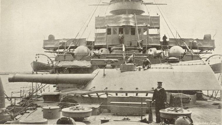
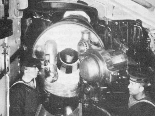
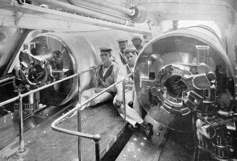
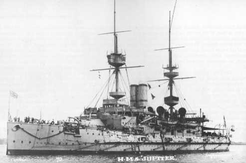
Also known as the "46-ton gun" (47 mt), these weapons were designed by the Royal Gun Factory at Woolwich Arsenal for the Majestic class and built by Vickers. Although this weapon represented a considerable reduction in caliber from the 13.5"/30 (34.3 cm) guns of the previous Royal Sovereign class, this was compensated for by better ballistics along with the greatly improved gun construction and a superior breech mechanism. It was also one of the first "wire-wound" guns to enter service. This construction method, which resulted in a much stronger barrel, was necessary as the introduction of cordite propellants resulted in significantly higher pressures.
Some of these weapons were reused on coastal monitors during World War I. Mountings removed from HMS Illustrious were used at the Kitchener and Roberts coastal batteries near the Tyne River in the 1920s.
During prize firing in 1904 HMS Majestic damaged two of her guns, including one which had about 13 inches (33 cm) of the liner blown out, even though she was firing with three-quarter charges at the time. This incident resulted in an inspection of all of these guns, leading to the discovery of the "steel choke" problem that was to plague British large caliber guns for the next decade. These faults limited the 12" (30.5 cm) guns to no more than 33 full charges until they had to be reworked. Nonetheless, these guns were considered to be excellent weapons.
Construction was inner A tube, A tube, wire wound, B tube, jacket and a screwed-on C ring over the join. Breech bush screwed onto A tube and a shrunk on collar that was screwed onto the A tube. The hand-operated breech completely detached from the barrel when opened and was held by a swing-back carrier. Actual length was 35.5 calibers.
A total of 75 Mark VIII guns plus five Mark VIIIv and four Mark VIIIe guns were manufactured. These latter guns were redesigns by Vickers and Elswick intended to correct the steel choke problem. The redesigned guns had thicker inner A and A tubes of nickel steel and deeper shoulders with cannelured rings, a shorter wire-wound section and improved securing of the rear of the A tube to the jacket. Mark VIII* denoted guns with the chamber front slope modified to prevent slip back at high elevations, but it appears that none were so altered.
| Designation | 12"/35 (30.5 cm) Mark VIII |
|---|---|
| Ship Class Used On | Majestic and Canopus classes
Sir John Moore (M5) Monitor class |
| Date Of Design | about 1890 |
| Date In Service | 1895 |
| Gun Weight | 46 tons (47 mt) including breech |
| Gun Length oa | 445.6 in (11.318 m) |
| Bore Length | 426 in (10.820 m) |
| Rifling Length | 349.29 in (8.872 m) |
| Grooves | (48) Straight section: 1.0 in deep x 0.62 in (2.54 mm x 15.7 mm)
(48) Twist section: 0.8 in deep x 0.607 in (20.3 mm x 15.4 mm) |
| Lands | N/A |
| Twist | RH Straight from start of rifling to 278.95 in (7.085 m) from muzzle then increasing to 1 in 30 at the muzzle |
| Chamber Volume | N/A |
| Rate Of Fire) | Majestic class (except Caesar and Illustrious): 1 round in 70 seconds until the ready rounds were gone and then 1
round in 100 seconds 1 Caesar, Illustrious and Canopus class (except Vengeance): 1.33 rounds per minute while ready supply lasted, much slower afterwards Vengeance: 1.9 rounds per minute while ready supply lasted, much slower afterwards Monitors: about 1.0 rounds per minute 2 |
- ^Caesar, Illustrious and the Canopus class had the improved BIII mounting (see below) which included two hydraulic rams for loading and other improvements. Vengeance added an improved chain rammer designed by Vickers which allowed any angle loading.
- ^Monitors generally fired no faster than one round per turret every minute.
- The firing mechanism was electric or percussion with vent sealed tubes and the guns could not be fired unless the breech was fully seated.
- The guns were designed for either a right or left hand breech, but the barrels were interchangeable.
| Type | Bag |
|---|---|
| Projectile Types and Weights 1a 2a 3a | AP 2crh - 850 lbs. (386 kg)
AP 4crh - 850 lbs. (386 kg) CPC 4crh - 850 lbs. (386 kg) HE 8crh - 873 to 878 lbs. (396 to 398 kg) HE 4crh - 850 lbs. (386 kg) Shrapnel 2crh - 850 lbs. (386 kg) 4a |
| Bursting Charge | AP - None
HE - 107 lbs. (48.5 kg) |
| Projectile Length | AP - N/A
HE - 48.3 in (122.7 cm) |
| Propellant Charge 5a | 1908: 174 lbs. (78.9 kg) Cord 50 + 3.75
1914: 174 lbs. (78.9 kg) Mark I 1914: 200 lbs. (90.7 kg) MDC45 1918 supercharge: 258 lbs. (117 kg) MDC45 |
| Muzzle Velocity | 850 lbs. (386 kg) shells - 2,350 fps (716 mps)
8crh HE shells with supercharge - 2,400 fps (732 mps) |
| Working Pressure | N/A |
| Approximate Barrel Life | Mark I propellant: 250 rounds
MD propellant: 500 rounds |
| Ammunition stowage per gun | 80 rounds |
- ^The sources below disagree as to the projectile weights, propellant types, propellant weights and muzzle velocities. This may be due to the rapid transition from black powder to cordite in the late 1800s and the attendant experimentation with differing mixtures. I have chosen to use those figures given in "The Big Gun" for AP rounds and those in "Big Gun Monitors" for HE rounds.
- ^HE 4crh and HE 8crh projectiles were issued only to monitors. The original AP 2crh was solid shot. The 8crh round was introduced in 1918.
- ^HE projectiles cost £14 and CPC about £25 before the war, with propellant costing an additional £20.
- ^Shrapnel rounds on the monitors were occasionally used with a time fuze as something of a makeshift AA round.
- ^Propellant was in four bags for all types.
| Elevation | Range |
|---|---|
| 13.5 degrees
With 2crh shells (Maximum elevation for Battleships) |
14,860 yards (13,590 m) |
| 30 degrees
With 4crh shells (Monitors only) |
22,870 yards (20,900 m) |
| Elevation | Range |
|---|---|
| 30 degrees and 2,400 fps (732 mps)
With 8crh shells and supercharge (Monitors only) |
26,000 yards (23,770 m) |
| Range | Vertical Iron Plate | Vertical Steel Plate | Vertical KC Plate |
|---|---|---|---|
| 1,000 yards (910 m) | 33 in (83.8 cm) | --- | --- |
| 3,100 yards (2,830 m) | --- | 12 in (30.5 cm) | --- |
| 10,000 yards (9,140 m) | --- | --- | 8.5 in (21.6 cm) |
Data for Iron and Steel from "British Battleships: 1850 - 1950." Data for KC from "Big Gun Monitors."
| Designation 1b | Twin Mount
Early Majestic (2): BII (Elswick) 2b Caesar (2), Illustrious (2), early Canopus (2): BIII (Whitworth) 3b Albion (2) and Glory (2): BIV (Elswick) 4b Vengeance (2): BV (Vickers) 5b Monitors (1): BII* |
|---|---|
| Weight | 184 tons (187 mt) 6b |
| Elevation | Battleships: - 3 / +13.5 degrees
Monitors: -0 / +30 degrees |
| Rate of Elevation | N/A |
| Train | about +150 / -150 degrees |
| Rate of Train | N/A |
| Gun Recoil | N/A |
| Loading Angle 7b | For Majestic class except for Caesar and Illustrious
13.5 degrees In addition, the mount needed to be trained to 0 degrees For other classes and for Caesar and Illustrious
Vengeance
|
- ^These mountings had thickly armored gunhouses, a significant improvement over the open barbettes of the previous Royal Sovereign class. The mounting series were of progressively better design, each one being used on a few ships until an improved version was available which in turn would be superseded by a newer version.
- ^The BII mountings were designed by Elswick and had shell and powder cages that were designed to terminate beside the rammers rather in line with them. When the cage reached the top it automatically dumped its load onto a 9 degree loading ramp leading to a bogie in line with the rammer. This arrangement allowed the cage to immediately return for the next round rather than having to wait for the end of the ramming cycle. The BII did not have a stalk but it did revolve around a fixed trunk that had two cages connected by a wire and driven by a drum such that when one cage was at gunhouse level the other was at the magazine level. The barbette for the BII was pear shaped and used an external rammer located in the barbette that restricted loading to 0 degrees train, similar to older designs. The BII was the first British mounting where the training mass was balanced about the center of rotation and the elevating mass was balanced about the trunnions, thus allowing for hand-training of the mounts as well as lighter training engines. This also meant that the ship did not list when the turrets were trained abeam. The guns themselves were also well-balanced, even when in the run out position, allowing for lighter elevating gear and hand-powered backup. These mountings were hydraulically powered. Typical manning was 47 officers and men. As originally built, the cost of a Mark BII mounting was £30,000 for the mounting and an additional £20,000 for the two guns.
- ^The BIII mounting was designed by Whitworth and had circular barbettes with the rammer in the gunhouse which allowed loading at any angle of train. These mountings did not have a stalk but now had a revolving shell room or working chamber below the gunhouse. With the elimination of the external rammer, the barbette could now be circular instead of pear shape, saving space and weight. In the latter Majestic class ships, the non-revolving trunk contained three independent cartridge hoists, a central access ladderway, two shell hoists and the hydraulic gear to operate the hoists. The shell hoists consisted of a bucket which lifted the projectiles vertically, nose down. The powder hoists had two compartments each holding a half-charge. These mountings were the first fitted to British ships that had a break in the ammunition supply, which gave them an increased safety factor. When the shells arrived at the working chamber, the shell was lifted vertically by a hydraulic hoist, picked up by a hydraulic crane and transferred horizontally to a waiting tray at the foot of a loading hoist. This ran on slanting beams up to the gunhouse and carried shell and cartridges up to the loading position, which was fixed at 13.5 degrees. A lever in the working chamber allowed the shell to roll sideways onto the loading tray where it was then rammed into the loading cage. The gunhouse had a three-stage telescope rammer, linked to a tray that extended to cover the breech threads. Three rounds per gun were stored in the gunhouse but loading and ramming of these had to be done manually. 24 ready rounds were stored in the working chamber. These allowed faster firing while they lasted as supply from the lower shell chambers was much slower. In the first three Canopus class ships, the ammunition supply system was changed such that the central trunk now had two combined shell and powder cages with the shells on top and the half charges below rather than separate cages for shell and cartridges.
- ^Designed by Elswick, the BIV mountings introduced a rotating stalk which extended from the gunhouse down to the magazine and shell rooms. The stalk had a combined shell and powder cage for each gun, arranged with the cartridges on top and the shell below. This came up behind the gun where the shell was rammed. Pulling a level allowed one cartridge to drop to the loading position where it could be rammed. This meant that the cage could not go back to the lower level until the gun was completely loaded, slowing the firing cycle. The stalk also contained two alternative single stage vertical shell and powder hoists which allowed loading even if the primary arrangements failed. This delivered shells nose-down to an alternative loading position fixed at +1 degree elevation. Three ready rounds per gun were stowed in the gunhouse and eight additional rounds per gun were stored in the working chamber.
- ^The BV mounting used only on Vengeance was designed by Vickers and was similar to the early BII mounting and shared the same handbook. This mounting was equipped with a new Vickers chain rammer that permitted loading at any angle of elevation and sped up the loading cycle. The gunhouses on Vengeance had angled plates rather than curved fronts and flat sides, which simplified manufacturing and set the pattern for subsequent ships.
- ^One source says the revolving weight was 264 tons (268 mt), which probably includes ammunition.
- ^Although normal loading of the Majestic class was at 0 degrees train, there was stowage for 16 ready-use rounds inside each gun shield. This allowed the guns to remain on target while using an auxiliary rammer rather than returning to 0 degrees train for reloading using the hydraulic rammer. When these mountings were modified for the monitors, the external rammer was removed which allowed an increase in stowage to 20 ready rounds in the gunhouse. However, when these were used up, the mounting did have to return to 0 degrees train in order to replenish the ready-use ammunition. Removing the original inclined rammer also allowed stowage for an additional 34 projectiles at the back of the barbette.
- The eight mountings for the monitors came from Victorious, Magnificent, Hannibal and Mars. These were reworked to allow +30 elevation in order to achieve the longer ranges needed for shore bombardments. This added elevation increased the recoil and run-out forces, requiring that higher hydraulic pressures be maintained. This led to frequent breakdowns, as the leather gaskets and brazed pipe joints could not handle the larger loads. Commented Rear Admiral Reginald Bacon, commander of the Dover Patrol, "Every day some pipe burst or some portion of the turret mountings gave out. The cause of these troubles was a simple one; these ships had turrets taken from old battleships of the [Majestic class]. Taken straight from these ships and mounted in the monitors, the copper pressure pipes, having become crystalline with age, did not stand the re-erection. New stresses during the fresh coupling up were set up and breakdowns occurred."


"Warrior to Dreadnought: Warship Development 1860-1905" and "The Grand Fleet: Warship Design and Development 1906-1922" both by D.K. Brown
"The Majestic Pre-Dreadnought" article by R.A. Burt in "Warship Volume VII"
"Big Gun Monitors: The History of the Design, Construction and Operation of the Royal Navy's Monitors" by Ian Buxton
"British Naval Guns 1880-1945 No 3" article by John Campbell in "Warship Volume V"
"The Big Gun: Battleship Main Armament 1860-1945" by Peter Hodges
"Find and Destroy: Antisubmarine Warfare in World War I" by Dwight R. Messimer
"British Battleships: 1860 - 1950" by Oscar Parkes
"Navy and Army Illustrated Annuals, Volume VI - 1898," Edition of 18 August 1898
---
Special Help from Dave Perkins
27 June 2008 - Benchmark
30 January 2009 - Added information about the monitors, added barrel life values, fixed minor typographical errors
09 March 2009 - Added additional information on monitors, added information on shrapnel, added costs of projectiles, guns and mountings
30 August 2011 - Added additional mounting information
15 October 2012 - Corrected typographical error
23 September 2016 - Converted to HTML 5 format
10 May 2021 - Reorganized notes

