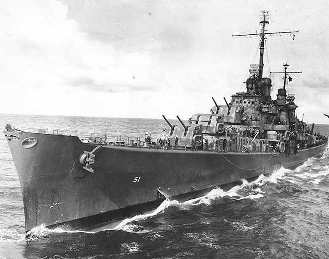
This was unquestionably the finest Dual Purpose gun of World War II. Originally designed to arm new destroyers being built in the 1930s, the 5"/38 (12.7 cm) wound up being used on nearly every major US warship built between 1934 and 1948 and was still being used on new construction as late as the 1960s. It was also used on many auxiliaries, merchant vessels and smaller warships as well as on US Coast Guard vessels. This standardization, unique in any navy, greatly helped the logistical supply situation of the Pacific War.
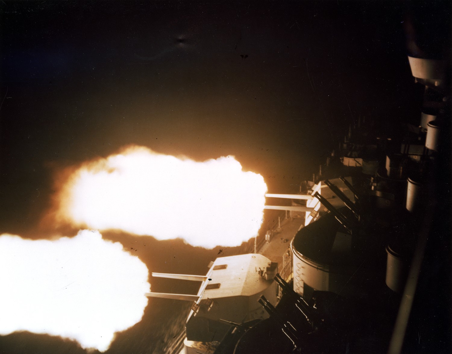
These guns were hand-loaded, but power-rammed, which gave them a high rate of fire and a capability of being easily loaded at any angle of elevation, both of which are highly desirable qualities for an anti-aircraft weapon. The introduction of proximity-fuzed AA shells in 1943 made this weapon an even more potent AAA gun.
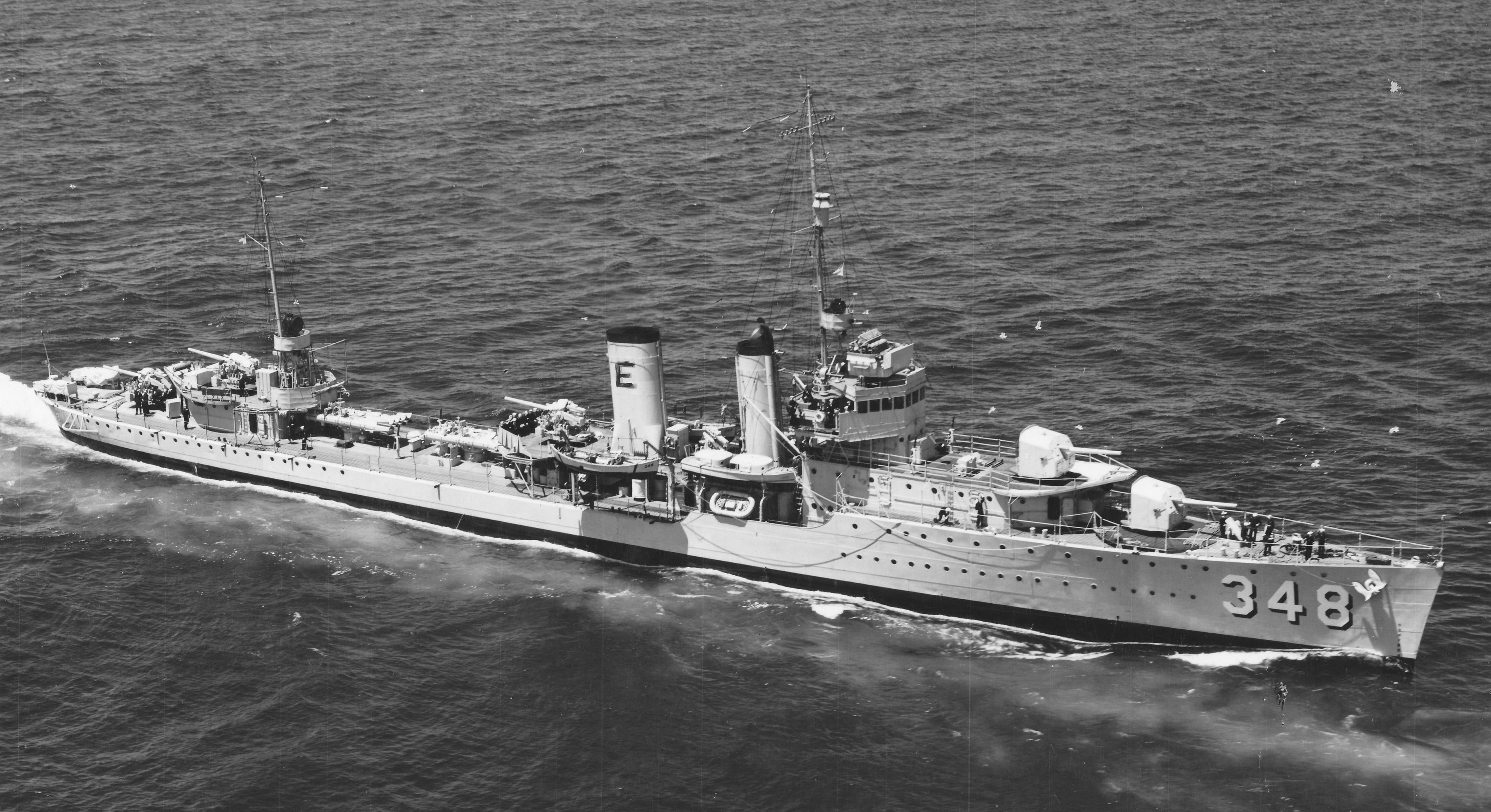
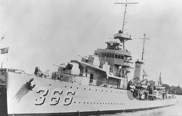
The earliest mountings as used on USS Farragut (DD-348) were pedestal mounts with the ammunition supply points located in the fixed structure behind the gun mounts. However, starting with USS Gridley (DD-380), a new base-ring mounting with integral shell hoists on the axis of the mount was introduced. This type of mounting meant that shells and cartridges could be passed directly to the gun's breech at any angle of train, thus significantly improving the practical rate of fire. Most subsequent designs, including all twin mountings, were similar, although simpler base ring mounts lacking hoists were introduced in 1943 for use on auxiliary vessels and escort carriers.
There were some teething troubles when this gun was introduced in 1934, but a BuOrd report of 1945 states that during World War II they were considered to be highly reliable, robust and accurate, a reputation they retained even after the end of the war when the 5"/54 (12.7 cm) series of weapons were introduced. When coupled with the Mark 37 Fire Control System, used on most US warships built between 1939 and 1946, these guns were also effective in the AA role. For example, during gunnery trials in 1941, USS North Carolina (BB-55) was able to repeatedly shoot down drone aircraft at altitudes of 12,000 to 13,000 feet (3,700 to 4,000 m), about double the range of the 5"/25 (12.7 cm) AA Mark 10 used on older ships.
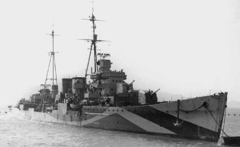
These guns were introduced to the British Royal Navy in 1941-1942 when HMS Delhi was rebuilt and rearmed at the New York Navy Yard. The British were impressed with the combination of the 5" (12.7 cm) gun and Mark 37 Fire Control System and tried to purchase additional units, but the rapid ramping up of US warship construction prevented any diversion. However, these guns were provided as part of the armament of the escort carriers and repair ships built in the USA for British use. In 1944, the British proposed that the Nelson class battleships replace their 6" (15.2 cm) and 4.7" (12 cm) mixed purpose batteries with six twin 5"/38 (12.7 cm) DP mountings, but this never proceeded past the planning stage.
At least twelve guns were sold to Brazil around 1940 for arming the Marcilio Dias class destroyers. At least 24 additional guns were sold to Brazil post-war for arming the Acre class destroyers.
Post-war, many US warships with these weapons were transferred to other nations where they served long after the last USN ship equipped with them had been retired.
The Mark A prototype for this gun was created from a cut-down 5"/51 (12.7 cm) Mark 9, the only version of that weapon that used semi-fixed ammunition.
Mod 0 was of autofretted monobloc construction and used a semi-automatic vertical sliding wedge breech mechanism. Mod 1 was similar but differed by having a longer keyway for the barrel locking key and a slightly modified chamber. Mod 1 was the most produced variant. Mod 2 used a non-expanded barrel of higher strength steel. For all Mods the gun barrel was secured to the housing by a bayonet joint, thus allowing easy barrel replacement without needing to dismount the gun.
Over 8,000 of these weapons were produced between 1934 and 1945, broken down as 2,168 guns in single mountings and 2,714 guns in twin mountings for warships plus 3,298 guns in single mountings for auxiliary ships and merchant vessels. These figures may not include guns produced prior to 1 July 1940, at which time there were 315 single DP, eight twin DP and 52 twin SP mountings in the entire US Fleet. Average cost was $100,000 per gun assembly, which does not include the cost of the mounting. Millions of rounds of ammunition were produced for these guns, with over 720,000 rounds still remaining in Navy storage depots in the mid-1980s.
| Designation | 5"/38 (12.7 cm) Mark 12 |
|---|---|
| Ship Class Used On | 1934 to 1948
First used on USS Farragut (DD-348) Used on nearly all World War II-era new-construction warships destroyer-sized and larger along with many auxiliaries, merchant vessels and small warships Also used to rearm older ships such as World War I-era battleships and USS Saratoga (CV-3) Use by other Nations
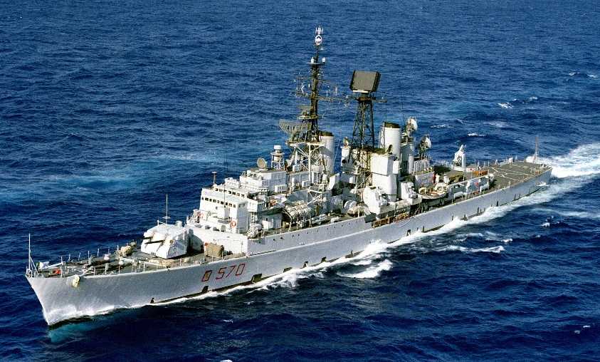
Britain: HMS Delhi as rearmed 1, Ameer class escort carriers, Assistance class repair ships Post-World War II USA: Brooke (FFG-1), Garcia (FF-1040), Long Beach (CGN-9) 2, Albany (CG-10) and USCG Hamilton (WHEC-715) classes Denmark: Peder Skram class frigates Italy: Impetuoso (D558) and San Giorgio (D562) classes |
| Date Of Design | about 1932 |
| Date In Service | 1934 |
| Gun Weight | 3,990 lbs. (1,810 kg) without breech |
| Gun Length oa | 223.8 in (5.683 m) |
| Bore Length | 190 in (4.826 m) |
| Rifling Length | 157.2 in (3.994 m) |
| Grooves | 45 |
| Lands | N/A |
| Twist | Uniform RH 1 in 30 |
| Chamber Volume | 654 in3 (10.72 dm3) |
| Rate Of Fire | Pedestal and other mounts lacking integral hoists: 12 - 15 rounds per minute
Base ring mounts with integral hoists: 15 - 22 rounds per minute |
- ^The guns installed on HMS Delhi had originally been destined for USS Edison (DD-439). These guns had been hand-picked by Edison's first commanding officer, LCDR Albert C. Murdaugh, who had just previously been assigned to the Naval Gun Factory at Washington, D.C. Much to LCDR Murdaugh's distress, President Roosevelt ordered these guns diverted to Delhi and as a result Edison did not receive her replacement guns until after she had been commissioned and had completed her preliminary trials. Perhaps as a result of having these hand-picked weapons, the gunnery officer on Delhi reported that during gunnery trials in February and March 1942 that these guns were able to fire 25 rounds per minute with the ready-use ammunition stored in the handling rooms and 15 rounds per minute with the normal supply from the magazines.
- ^I believe that USS Long Beach (CGN-9), decommissioned in 1994, was the last active USN ship to carry 5"/38 (12.7 cm) guns.
- Barrel was chrome plated from the muzzle to include all rifling, the projectile band slope and the forward portion of the chamber. Total length of plating was 164.5 in (4.178 m) for Mod 0 and 162.25 in (4.121 m) for Mod 1. Plating was 0.00050 in (0.0127 mm) thick.
- Projectile travel was 161.34 inches (4.098 m).
- These guns had a gas ejector system which blew compressed air into the breech after each shot.
| Type | Separate |
|---|---|
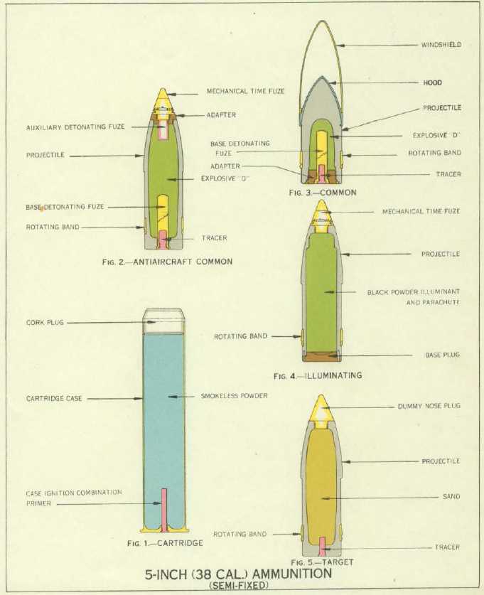
| Projectile Types and Weights 1a | AAC Mark 34 Mod 10: 55.18 lbs. (25.0 kg)
AAC Mark 35 Mods 1 to 12: 55.18 lbs. (25.0 kg) AAC Mark 47 Mods 0 and 1: 55.18 lbs. (25.0 kg) AAC Mark 49: 55.18 lbs. (25.0 kg) AAC Mark 52: 55.18 lbs. (25.0 kg) AAC Mark 56: 55.18 lbs. (25.0 kg) Common Mark 32 Mods 1 to 4: 54.0 lbs. (24.5 kg) AAVT Mark 31 Mods 1 to 11: 55.12 lbs. (25.0 kg) Special Common Mark 38 Mods 1, 2 and 3: 55.18 lbs. (25.0 kg) Special Common Mark 46 Mods 1 and 2: 55.18 lbs. (25.0 kg) RAP Mark 57 2a: 54.3 lbs. (24.6 kg) Illum 3a Marks 27, 30, 44 and 45 - 54.39 lbs. (24.7 kg) WP Mark 46: 53.00 lbs. (24.0 kg) Chaff Mark 78: 55.3 lbs. (25.1 kg) |
| Bursting Charge | AAC Mark 34: 7.25 lbs. (3.3 kg) Explosive D or Composition A
AAC Mark 35: 7.25 lbs. (3.3 kg) Explosive D or Composition A AAC Mark 47: 7.11 lbs. (2.8 kg) Explosive D or Composition A AAC Mark 52: 7.5 lbs (3.4 kg) Explosive D or Composition A AAC Mark 52: 8.4 lbs. (3.8) kg Composition A-3 AAC Mark 56: 7.5 lbs. (3.4 kg) Explosive D or Composition A AAVT Mark 31: 7.25 lbs. (3.3 kg) Explosive D or Composition A Special Common Mark 38: 2.04 lbs. (0.9 kg) Explosive D Common Mark 32: 2.58 lbs. (1.2 kg) Explosive D RAP: 3.5 lbs. (1.6 kg) Explosive D |
| Projectile Length | AAC: 20.75 in (52.7 cm)
Common: 20.75 in (52.7 cm) AAVT: 20.75 in (52.7 cm) Special Common: 20.75 in (52.7 cm) Illum: 20.0 in (50.8 cm) WP: 20.0 in (50.8 cm) |
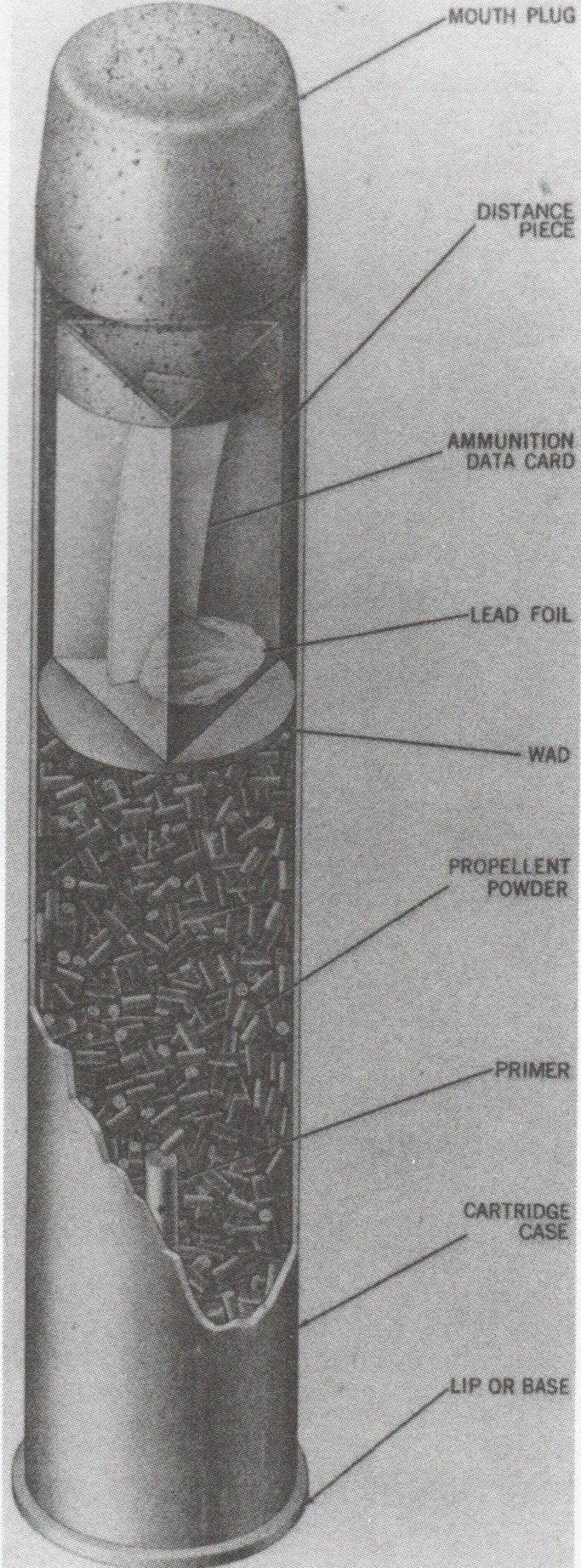
| Cartridge Case Type, Size and Empty Weight | Marks 5, 8 and 10: Brass, 127 x 679 mm, 12.31 lbs. (5.58 kg)
Mark 5 Modified 4a: Brass, 127 x 413 mm, N/A |
| Propellant Charge 5a | Full Charge: 15.2 to 15.5 lbs. (6.9 to 7.03 kg) SPD or SPDN D272
Full Charge: 17.2 lbs. (7.8 kg) Universal D264 Full Flashless Charge: 16.0 lbs. (7.3 kg) SPDF D274 Reduced Charge: 3.6 lbs. (1.6 kg) SPDN D282 |
| Muzzle Velocity | Full Charge: New gun: 2,600 fps (792 mps)
Full Charge: Average gun: 2,500 fps (762 mps) Reduced Charge: New gun: 1,200 fps (366 mps) |
| Working Pressure | 18.0 tons/in2 (2,835 kg/cm2) |
| Approximate Barrel Life | 4,600 rounds 6a |
| Ammunition stowage per gun 7a 8a | Yorktown (CV-6) and Essex (CV-9): 450 rounds
North Carolina (BB-55), South Dakota (BB-57) and Iowa (BB-61): 450 rounds Alaska (CB-1): 500 rounds Baltimore (CA-68), Oregon City (CA-122) and Des Moines (CA-134): 500 rounds Saint Louis (CL-49), Cleveland (CL-55) and Fargo (CL-106): 500 rounds Atlanta (CL-51): 450 rounds Pre-war destroyers of the Farragut (DD-348) through Sims (DD-409) classes: 300 rounds Benson (DD-421) and Gleaves (DD-423): 360 rounds Fletcher (DD-445): 425 rounds (575 in later ships) Allen M. Sumner (DD-692) and Gearing (DD-710): 460 rounds John C. Butler (DE-339): 325 rounds Garcia (FF-1040) and Brooke (FFG-1): 350 rounds Others: N/A |
- ^Special Common had a windscreen with a thin hood and the body was strengthened to enhance its armor piercing qualities. Postwar, some Special Common were given a dye bag for spotting. Available colors were blue, green, orange and red. Common Mark 32 had a windshield but no cap. AAC Mark 35 and Mark 49 projectile bodies could be used with Point Detonating (PD), Mechanical Time (MT) or with proximity (VT) nose fuzes. When issued with MT or VT fuzes they were considered as being AA rounds, but when issued with PD fuzes, they were considered to be HC rounds. Changing the fuze also resulted in slight changes in the total projectile weight and burster weight. For example, the Mark 35 with a PD fuze weighed 54.3 lbs. (24.63 kg) total with a 7.55 lbs. (3.42 kg) burster. Controlled Variable Time (CVT) fuzes were introduced post-war. AAC Mark 35 could also be issued as B.L.&P. or as B.L.&T. for target practice. Projectiles that used MT or PD nose fuzes had an instantaneous contact type base fuze while a blind plug was used in place of the base fuze for those projectiles using VT nose fuzes. The AAC Mark 47 was designed as a heavier projectile using new, lighter weight fuzes so as to maintain the same overall projectile weight. However, the fuzes never appeared, so only a few thousand of the Mark 47 projectiles were manufactured. Window and White Phosphorous (WP) rounds were available, many as special Mods of the Illumination Mark 30, Mark 44 and Mark 45 projectile bodies. Chaff rounds were available for jamming different radar types. Chaff Load Mark 15 was for X-band while Chaff Load Mark 21 was intended for S-band. Chaff projectiles used a MT nose fuze that triggered a small ejection charge and the loads were dispensed through the base of the projectile.
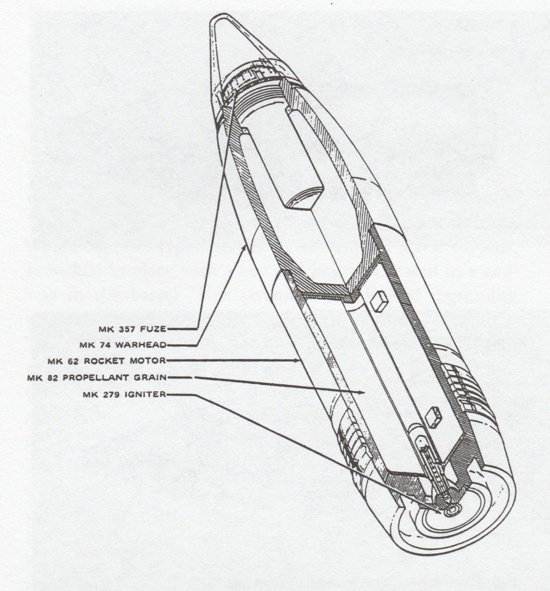
- ^The Rocket Assisted Projectile (RAP) round was developed during the 1960s. The rocket engine burned for 40 seconds.
- ^The illumination rounds burn for approximately 50 seconds.
- ^Cartridge Case Mark 5 Modified was used for Reduced Charges and could hold up to 9.0 lbs. (4.1 kg) of propellant. It was also shorter than the standard casing so that it could be used should a projectile jam in the rifling before it was fully seated. The reduced charge in this casing would give a "softer blow" to the jammed projectile as a safety measure.
- ^Some SPD propellant charges had flashless pellets added which gave them a "reduced" flash.
- ^During the Okinawa campaign, so much 5"/38 (12.7 cm) ammunition was expended in such a short period of time that concerns were raised regarding excessive barrel wear. Two Fletcher class destroyers, USS Hall (DD-583) and USS Richard P. Leary (DD-664), the latter of which had expended about 4,270 rounds per gun, were ordered to perform an offset practice shoot to determine the effects of barrel wear on accuracy. The exercise found that the range patterns from USS Richard P. Leary were 260 yards at 6,000 yards (240 m at 5,500 m) and 470 yards at 12,000 yards (430 m at 11,000 m), which were both within the nominal accuracy specifications.
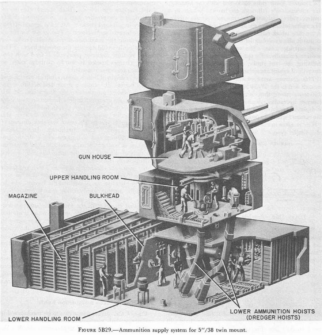
- ^Outfits listed are the design figures. Pre-war destroyers normally carried about 100 to 150 rounds per gun plus 100 - 120 illumination rounds per ship with the balance carried in magazines on Destroyer Tenders (AD). After 1940, outfits for most destroyers were increased to the design figure plus about 200 illumination rounds per ship. As the war went on, ammunition stowage on new designs was increased where possible. Some examples: Late war Fletcher (DD-445) class carried 525 rounds per gun in magazines plus 50 ready rounds per gun (these totals may include illumination rounds). The A.M. Sumner (DD-692) class carried 352 rounds per gun in magazines plus 50 ready rounds per gun. The A.M. Sumner class also carried 292 illumination rounds per ship in magazines plus 48 ready illumination rounds per ship. This was same capacity for the Gearing (DD-720) and Robert H. Smith (DM-23) classes. This large increase in ammunition weight over the design figures resulted in destroyers losing two to four knots in maximum speed from the design specifications. However, the stowage for pre-war destroyers could not be so greatly increased. For example, the Farragut class destroyer USS Aylwin (DD-355) had about 250 rounds per gun in magazines plus 50 ready rounds per gun in 1944. The rebuilt USS Selfridge (DD-357), which had traded her eight SP guns for five DP guns after receiving torpedo damage in 1943, carried about 43 ready rounds per gun and 260 rounds per gun in magazines. She also carried 22 ready illumination rounds per gun and 85 illumination rounds in magazines. By 1945, the new battleships in their magazines carried 500 rounds per gun, primarily AA Common and AA VT, plus 40 special types per gun. In addition, they had 55 ready rounds per gun. The older battleships that had replaced their mixed secondary batteries with a uniform battery of 5"/38 (12.7 cm) guns were able to store roughly the same number of rounds of ammunition as they had for the older guns. For example, USS Nevada (BB-36) during the Normandy operations in 1944 carried an outfit of 7,426 AA Common rounds (equivalent to 464 rounds per gun) vs. 4,830 5"/51 (12.7 cm) rounds and 2,400 5"/25 (12.7 cm) rounds. Ready rounds for all ships with base ring mounts were stored in the upper handling rooms which were located directly beneath each mount. Ships with pedestal-mounted guns had their ready rounds in splinter-proof boxes located near the guns.
- ^Outfits for most ships during the early part of World War II consisted primarily of AA Common plus illumination rounds. As noted above, changing the nose fuze type allowed these rounds to be used as AAC or as HC. The Porter (DD-356) and Somers (DD-381) classes as originally built with SP guns carried mostly Common rounds, but they did carry a few AA Common rounds which were intended for use against torpedo bombers and other low-flying planes. Starting in late 1942, AA VT projectiles were introduced and became increasingly available as the war went on. By the middle of 1944, most front-line ships had about three AA VT rounds for every one AA Common round. The usual practice was to fire this ratio at attacking aircraft. The smoke puffs created by the time-fuzed AA Common rounds allowed the fire control officers to assess and correct the accuracy of the firing control solution and also provided target guidance for the gun crews of the shorter-ranged 40 mm and 20 mm AA guns. VT fuzing reduced roughly in half the number of rounds fired per aircraft shot down. A notable success with VT ammunition was that of USS Abercrombie (DE-343) which shot down a Ohka (Baka) rocket glider bomb in May 1945, firing only two rounds.
- Rounds were normally 5.25crh. Some rounds may have been slightly boat-tailed.
- The cartridge cases were sealed with cork plugs which extended about 2.5 in (6.4 cm) past the mouth of the case.
- Projectiles leave the barrel rotating at about 208 RPS.
- In the early 1950s an anti-submarine projectile designated as EX-30 was under development. This was a long, fin-stabilized projectile weighing 75.0 lbs. (34.0 kg) and with a muzzle velocity of 300 to 500 fps (91 to 152 mps) intended to be used against submarines within 2,000 yards (1,830 m). The propellant was inserted between the shrouded tail fins. Initial testing in 1952 was successful but the project was not further developed.
- Bourrelet diameter was 4.985 inches (12.66 cm).
- Post-war, Brazil, Spain and Turkey set up manufacturing facilities to produce munitions to USN specifications.
| Elevation | Range | Angle of Fall | Time of Flight | Striking Velocity | Maximum Ordinate |
|---|---|---|---|---|---|
| 0.44 degrees | 1,000 yards (914 m) | 0.47 degrees | 1.21 seconds | 2,365 fps (721 mps) | 6 ft (1.8 m) |
| 0.44 degrees | 2,000 yards (1,829 m) | 0.93 degrees | 2.55 seconds | 2,141 fps (653 mps) | 26 ft (7.9 m) |
| 2.18 degrees | 4,000 yards (3,658 m) | 2.85 degrees | 5.71 seconds | 1,725 fps (526 mps) | 130 ft (40 m) |
| 3.89 degrees | 6,000 yards (5,486 m) | 5.97 degrees | 9.67 seconds | 1,372 fps (418 mps) | 377 ft (115 m) |
| 6.34 degrees | 8,000 yards (7,315 m) | 11.10 degrees | 14.73 seconds | 1,128 fps (344 mps) | 890 ft (271 m) |
| 9.79 degrees | 10,000 yards (9,144 m) | 18.33 degrees | 20.81 seconds | 1,003 fps (306 mps) | 1,825 ft (556 m) |
| 14.33 degrees | 12,000 yards (10,972 m) | 26.63 degrees | 27.78 seconds | 950 fps (290 mps) | 3,350 ft (1,021 m) |
| 20.06 degrees | 14,000 yards (12,802 m) | 35.38 degrees | 35.81 seconds | 942 fps (287 mps) | 5,645 ft (1,721 m) |
| 27.47 degrees | 16,000 yards (14,630 m) | 44.60 degrees | 45.44 seconds | 963 fps (294 mps) | 9,070 ft (2,765 m) |
| 43.30 degrees | 18,200 yards (16,642 m) | 59.37 degrees | 64.40 seconds | 1,030 fps (314 mps) | 17,750 ft (5,410 m) |
| 64.23 degrees | 14,000 yards (12,802 m) | 73.40 degrees | 84.20 seconds | 1,057 fps (352 mps) | 29,650 ft (9,037 m) |
| 72.20 degrees | 10,000 yards (9,144 m) | 78.57 degrees | 93.70 seconds | N/A | 33,430 ft (10,189 m) |
| 79.60 degrees | 6,000 yards (5,486 m) | 83.32 degrees | 99.30 seconds | N/A | 36,040 ft (10,985 m) |
| 83.17 degrees | 4,000 yards (2,688 m) | 85.60 degrees | 100.60 seconds | N/A | 36,900 ft (11,247 m) |
| 85.00 degrees | 2,940 yards (2,688 m) | 86.78 degrees | 100.90 seconds | N/A | 37,220 ft (11,339 m) |
- ^Values from BuOrd OP 551.
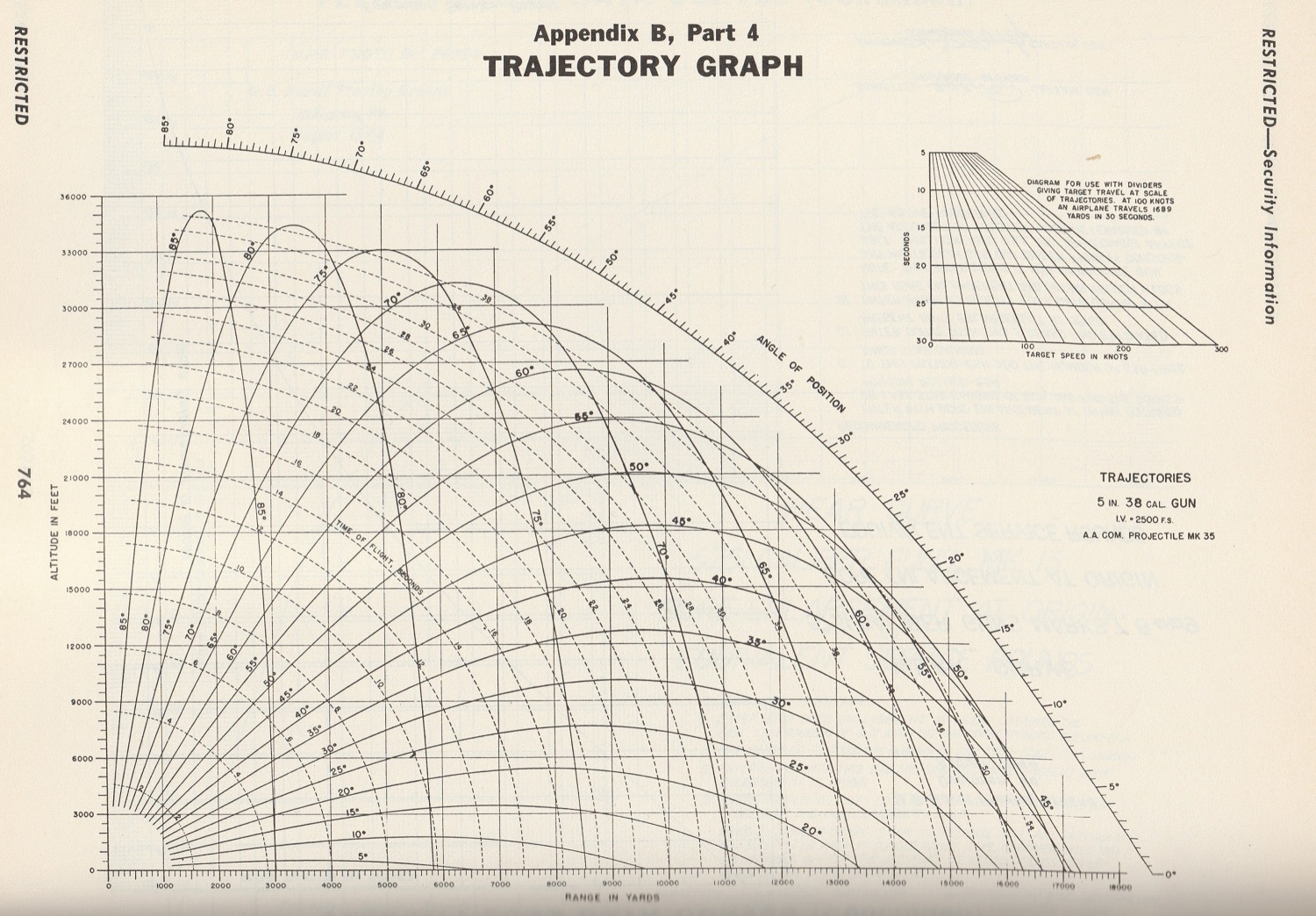
- For other range information, see the Trajectory Chart below.
- RAP round had a maximum range of 23,770 yards (21,735 m).
| Range | Side Armor | Deck Armor |
|---|---|---|
| 4,000 yards (3,660 m) | 5.0" (127 mm) | --- |
| 5,400 yards (4,940 m) | 4.0" (102 mm) | --- |
| 7,400 yards (6,770 m) | 3.0" (76 mm) | --- |
| 11,000 yards (10,060 m) | 2.0" (51 mm) | --- |
| 13,800 yards (12,620 m) | --- | 1.0" (25 mm) |
- These figures are taken from USN armor penetration curves published in 1942 as shown in "US Naval Weapons".
- It should be noted that US ships during World War II carried only small quantities of Special Common ammunition as the AA Common projectiles were considered to be more useful against a greater variety of targets.
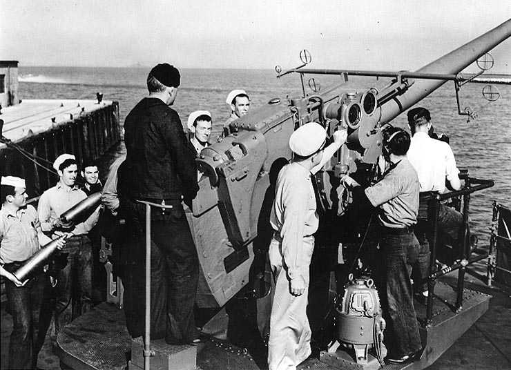
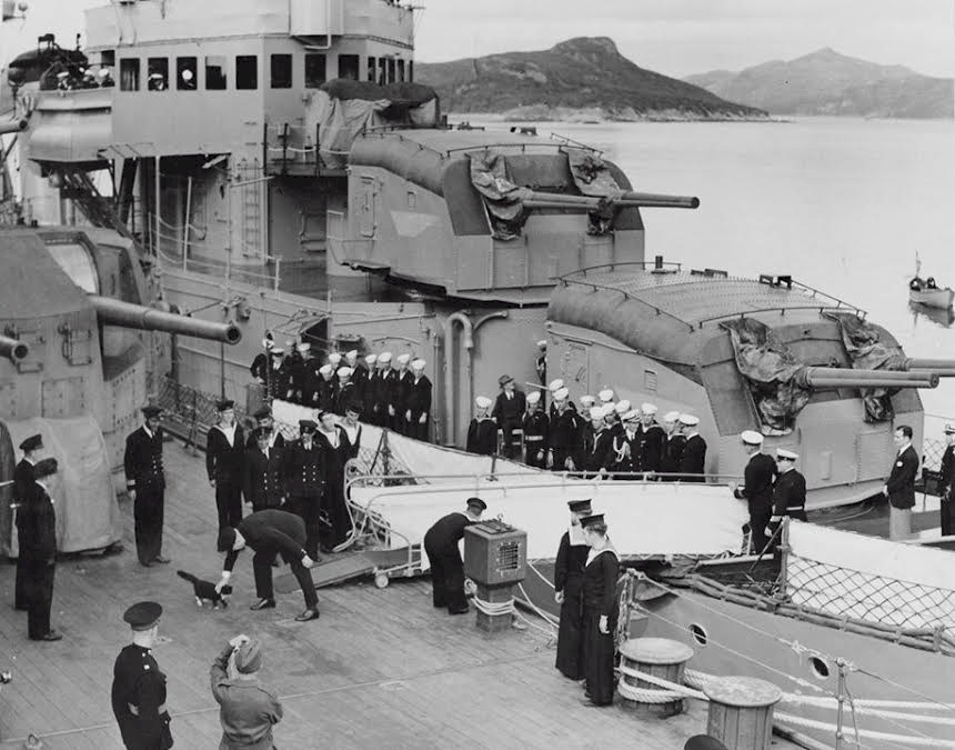
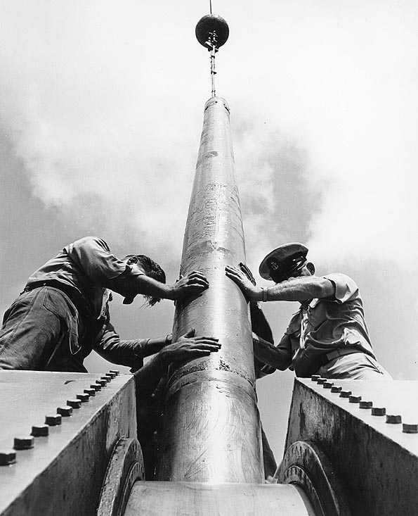
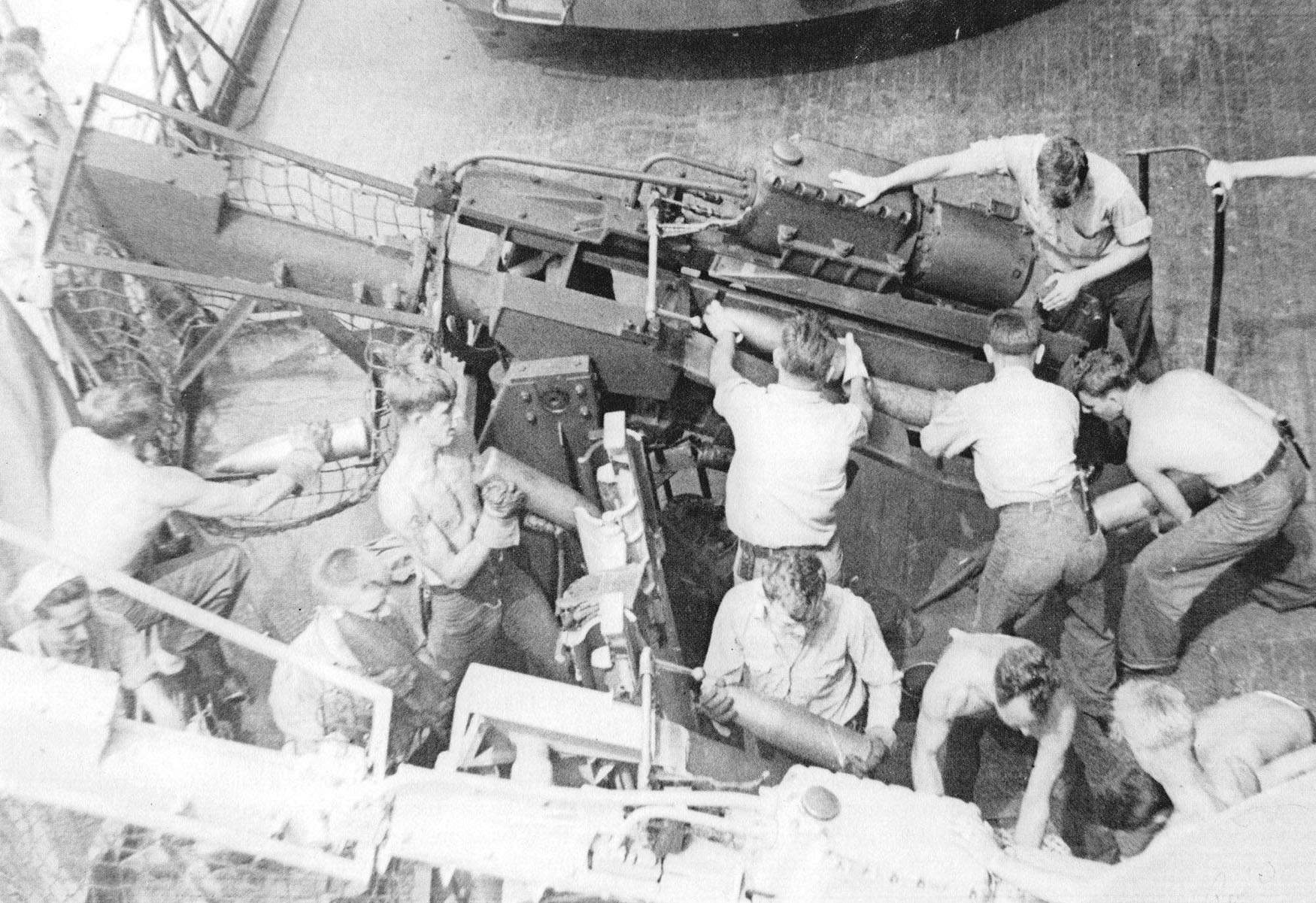
The drill projectiles being held by the two sailors on the left are of interest. The major difference between the 5"/38 (12.7 cm) Mark 12 and its AA predecessor, the 5"/25 (12.7 cm) Mark 10 was its use of semi-fixed (separate) ammunition rather than fixed ammunition. U.S. Naval Historical Center Photograph # NH 80-G-22246.
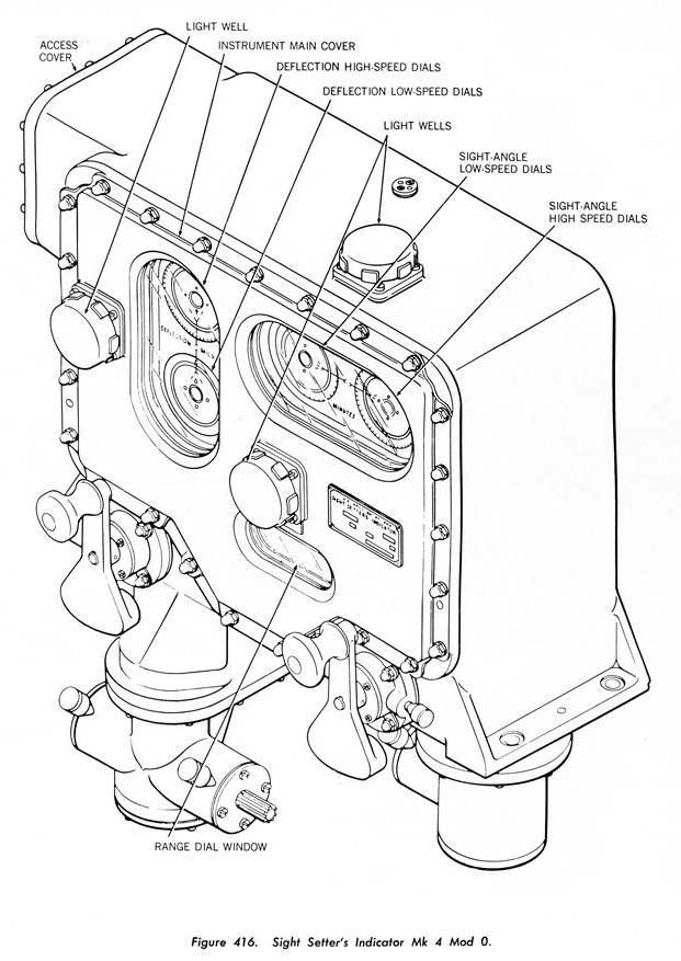
In the photograph of USS Shaw (DD-373) at right, the officer is pointing to the three circular dials that form the Sight Setting Dial Cluster. The enlisted man with the head phones standing next to him is the "Sight Setter" who operated the Sight Setting dials. These dials were "follow the pointer" indicators which showed the deflection angle (bearing) in the LH glass face dial and the sight angle (superelevation) in the RH glass face dial while the range was shown by the bottom metal face dial. Inside each of the two glass-face dials were two smaller dials - an inner disc dial mounted on a synchro motor shaft and an outer ring dial inscribed with a scale. The inner disc dial synchro motors were operated from the fire control computer and showed the desired sight angle and deflection angle as calculated by the computer. The outer ring dials, controlled by the Sight Setter via two hand cranks, showed the current sight angle and deflection angle of the gunsights. The bottom dial was the range indicator with the black slot on the right being the readout location, showing the range in yards. The range dial and the sight angle dial were geared together to work from the same hand crank.
The job of the Sight Setter was to ensure that the two dials in each indicator were in line with each other before the gun was fired in automatic mode (which is where the command "match pointers and shoot" comes from). He did this by turning his two hand cranks. Turning these hand cranks moved the prisms in the gunsights used by the trainer and pointer such that, when the gun was trained and elevated to match the sight setter, their crosshairs would be on the target. In local control, the sight setter was directed by the mount captain as to the proper settings to be used.
Other interesting features in this photograph are the prominent open sights above the gun and the electric rammer/counterweight at the breech end of the weapon.
The second image is for the Sight Setter Indicator as used on twin mounts. Its operation and use was similar to the previous instrument, but differed by having both a high speed dial and a low speed dial for the deflection and sight angles. Each of these dials had its own synchro motor.
For more information on how Sight Setting worked, please see this excellent video by Tom Scott of Battleship Texas describing the 5"/51 (12.7 cm) gun design and how it operated.
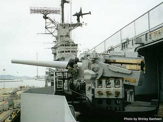
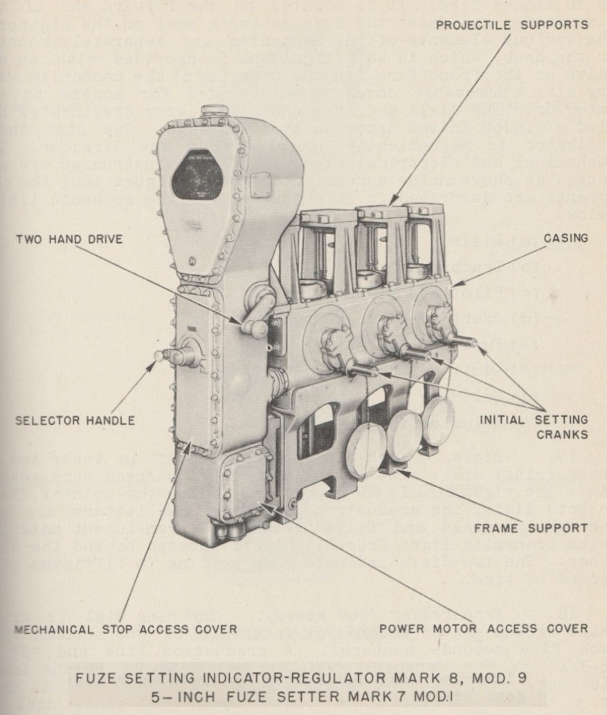
The photograph and illustration at right show a Mechanical Fuze Setter on the side of the gun platform and the Fuze Setting regulator used on them. These Mechanical Fuze Setters were installed on those mounts lacking integral hoists and were used to set the mechanical time fuzes (MT) on AA projectiles. Projectiles were inserted nose-down into the slots on this machine.
The Fuze Setter crewman watched two dials on the Mechanical Fuze Setter, a "Zero-Reader" (low-speed) dial and a "Follow-the-Pointer" (high-speed) dial that together indicated the total fuze time. The Zero-Reader dial is graduated from 0 to 45 seconds in 1 second intervals and goes up to 48.75 seconds. The Follow-the-Pointer dial is graduated from 0 to 1 second twice around the dial in 0.02 second intervals. In brief, the Mechanical Fuze Setter could set the fuze time anywhere between 0.80 seconds and 48.75 seconds in 0.02 second increments. The 0.80 seconds minimum setting was a safety factor to ensure that the fired shell would not explode until it was a safe distance away from the ship.
Each of these dials on the Fuze Setter had an inner dial that was driven by the analog computer in the fire control system, such as the Mark 1 computer used with the Mark 37 Gun Fire Control System (GFCS). The Fuze Setter could be used in either Automatic Mode or in Manual Mode as controlled by the Selector Handle. In Automatic Mode, the computer controlled the fuze time without manual interaction. In Manual Mode, the Fuse Setter Crewman used the Hand Cranks to move the outer dials to set the fuze time that was either sent by the computer (again, this is where the command "match pointers and shoot" comes from) or as ordered by the Gun Captain. Note that there are effectively two forms of Manual Mode. The first is where the computer sends the time to the Fuze Setter, but does not automatically control the fuze setting, this being done manually by the Fuze Setter Crewman. The second is where the computer is not used at all and the Fuze Setter Crewman, as directed by the Gun Captain, controls the fuze setting.
As can be seen in these pictures, the Mechanical Fuze Setter had three projectile slots. The ammunition passers placed each projectile nose-down into one of the slots, fitting the fixed lug on the fuze (see illustration below) into the V-groove in the slot. Each slot had a rotating cup with a pawl that engaged the time ring lug on the projectile. Moving this ring set the fuze time. Once the projectile was in place, the ammunition passer turned the crank located below the cup which rotated the cup and thus the fuze time ring to the initial setting. Afterwards, the Mechanical Fuze Setter would continually rotate the nose cups to match the latest time setting as determined by the computer (Automatic Mode) or by the Fuze Setter Crewman (Manual Mode). Having three slots allowed enough time for each successive projectile to be set to the proper time setting before the shell man (first loader) picked it out of the machine and placed it into the gun loading tray. This method of fuze setting also allowed the time fuzes to be continually updated by the computer until the moment they were plucked from the machine, thus ensuring the best possible setting for each individual shell and minimizing the "deadtime" interval between when a shell was plucked from the Mechanical Fuze Setter and when it was fired out of the gun.
The first loader stepped on a foot pedal to lift the shell out of the nose cup mechanism as he pulled the shell out of the Fuze Setter.
When firing VT Fuzed (Proximity) AA projectiles, there was no need to set the time as the VT fuze itself determined when the projectile should detonate. The post-war Controlled Variable Time (CVT) Fuze did use a time setting which delayed enabling the fuze until a few seconds before it reached the target. This reduced the chances that rain or sea return would cause a premature detonation.

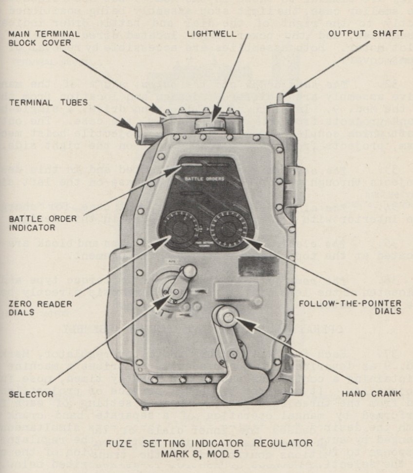
The Fuze Setter Regulator for integral hoists on single mountings was located on the forward face of the upper end of the projectile hoist. For twin mounts, a single Regulator was located between the guns in the forward portion of the gunhouse, controlling the fuzes for both guns. The Regulator for the integral hoists operated in a similar manner to the one described above, but differed in that it had a single hand crank for manually setting the fuze time and in that it had a Battle Order Indicator. This indicator had two lines of Battle Orders that were magnetically operated by the GFCS. The Upper Line indicated the mode of the gun while the Lower Line indicated the type of ammunition to be fired.
| Upper Line | Lower Line |
|---|---|
| Fire | Anti-Aircraft |
| Cease | Illuminating |
| Load Hoist | Common |
| Circuit Broken | Dive Attack |
The "Circuit Broken" signal shows in red and appears when there is a failure of the Battle Order System power supply. My understanding is that "Dive Attack" was used in Manual Mode and meant that all projectiles were to be set to the same time in order to create a barrage pattern.
| Designation 1e | Single Open or Open-back Shield Pedestal Mounts
Farragut (5) and Mahan 2e (5): Mark 21 3e Yorktown (8) and Enterprise (8): Mark 21 Mod 16 4e Improved Open Pedestal Mounts
Single Enclosed Base Ring Mounts
Single Open Base Ring Mounts
Twin Enclosed Base Ring Mounts 12e
Use by other Nations
Britain
Postwar Construction Single Open
Single Enclosed
Twin Enclosed
|
|---|---|
| Weight 20e | Single Open Pedestal Mounts
Mark 21 Mod 0: 29,260 lbs. (13,272 kg) (no shield) Mark 21 Mod 1: 31,520 lbs. (14,297 kg) (half shield) Mark 24 Mod 0: 31,200 lbs. (14,152 kg) Single Open Base Ring Mounts
Single Enclosed Base Ring Mounts
Twin Enclosed Base Ring Mounts
|
| Elevation 21e | Single Mounts
All with the following exceptions -15 / +85 degrees Mark 24 Mod 11: -10 / +85 degrees Mark 30 Mod 51: -5 / +85 degrees Mark 30 Mod 80: -15 / +27 degrees Twin Mounts
|
| Elevation Rate | Single Mounts
Mark 21: 5 degrees per handwheel turn (original manual operation) Mark 21: about 15 degrees per second (wartime addition of power operation) Mark 24: 15 degrees per second Mark 25: 15 degrees per second Mark 30 with GE controls: 15 degrees per second Mark 30 with Ford controls: 18 degrees per second Mark 37: 15 degrees per second Twin Mounts
|
| Train | Destroyers
Depending upon position, arc of 284 degrees up to an arc of 330 degrees Cruisers and Capital ships
|
| Train Rate | Single Mounts
Mark 21: 10 degrees per handwheel turn (original manual operation) Mark 21: about 25 degrees per second (wartime addition of power operation) Mark 24: 28.75 degrees per second Mark 25: 28.7 degrees per second Mark 30 with GE controls: 28.75 degrees per second Mark 30 with Ford controls: 34 degrees per second Mark 37: 30 degrees per second Twin Mounts
|
| Loading Angle 22e | Any |
| Gun recoil 23e | 15 in (38 cm) |
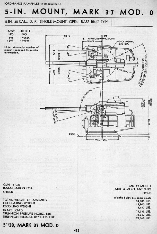
- ^The mounting types, designations and quantities shown in this table are primarily for warships "as commissioned" and are mainly the result of my research for a History and Technology essay on US gun mounting production during World War II. These quantities, Mark and Mod numbers may not be in agreement with some of the published works listed below, but I believe them to be correct based upon my research. Besides those ships listed above, this weapon was extensively used on auxiliaries and merchant ships as well as on US Coast Guard ships.
- ^2.12.22.3Two USS Mahan (DD-364) class destroyers, USS Dunlap (DD-384) and USS Fanning (DD-385), were completed with two Mark 25 enclosed mountings on their bows and three Mark 24 pedestal mounts on their sterns. As such, they formed a sub-class within the Mahan class, as all other members of that class were equipped with Mark 21 pedestal mounts in all five positions.
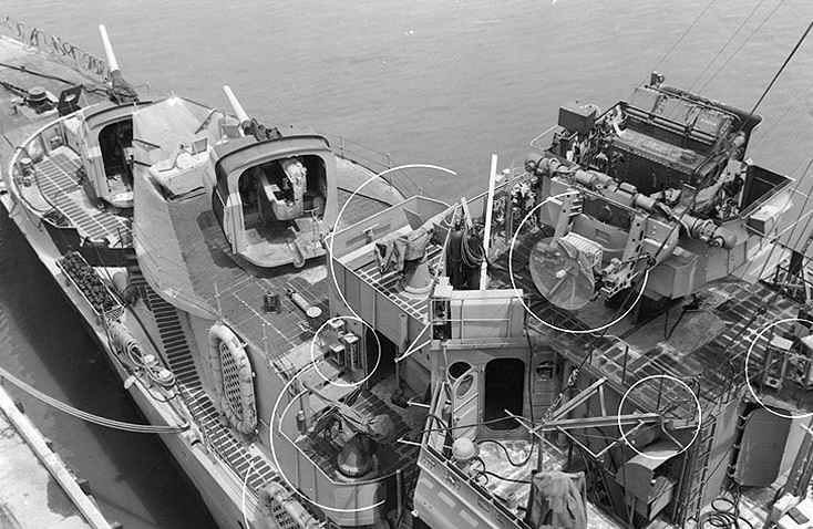
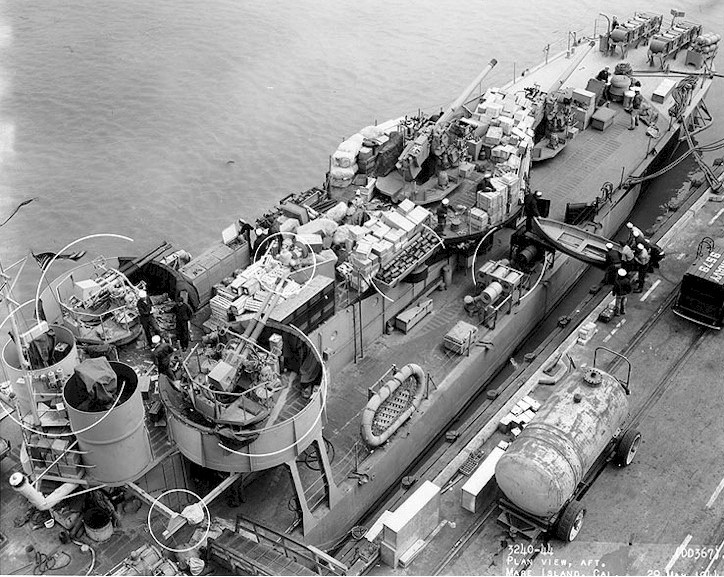
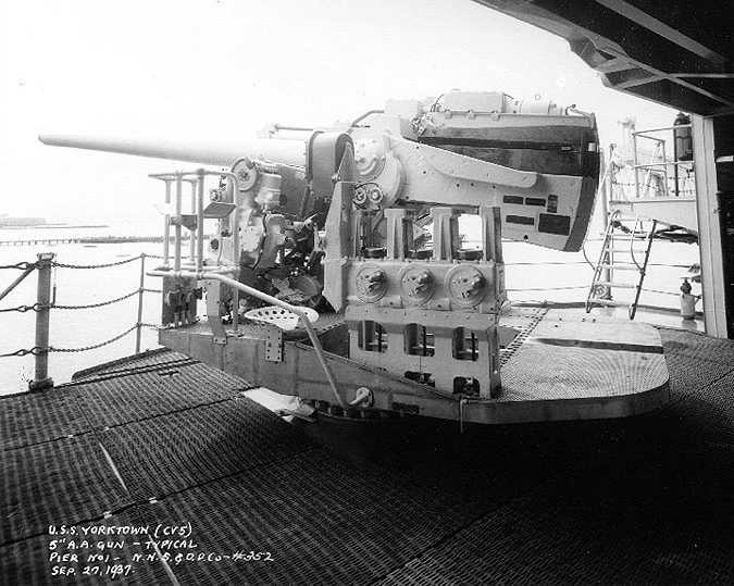
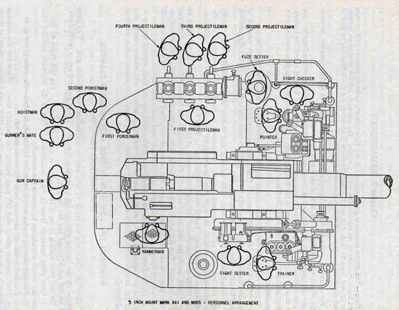
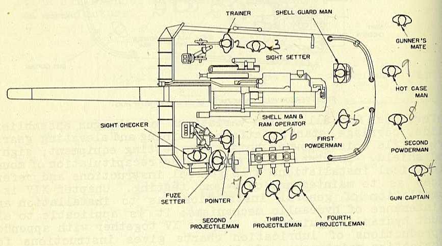
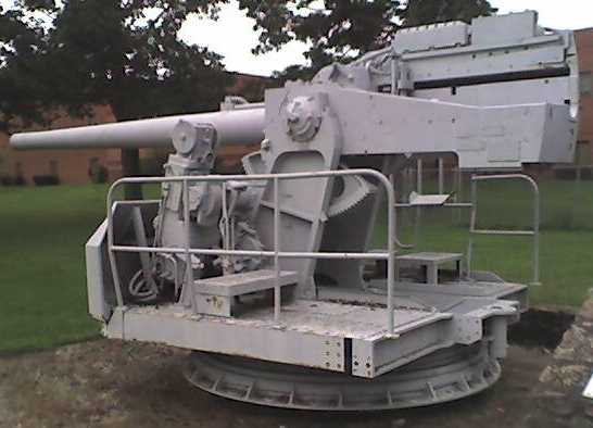
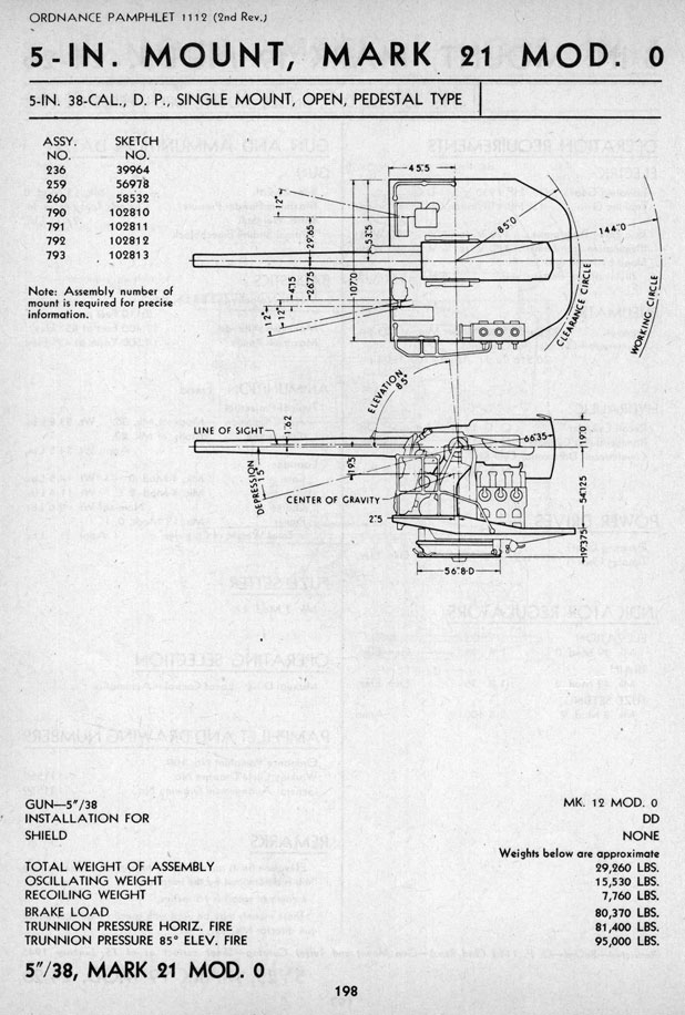
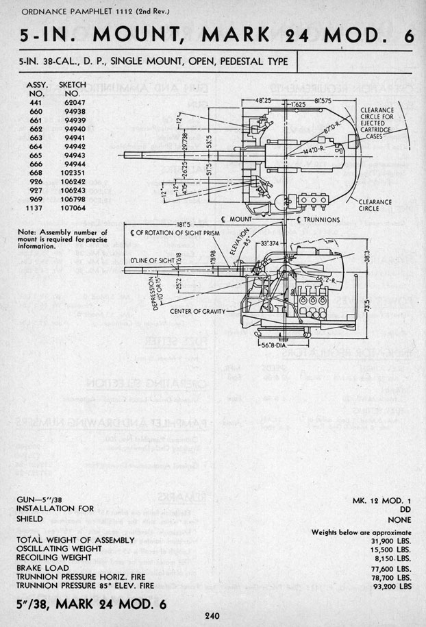
- ^The Mark 21 pedestal mount was at the limit of turning masses that could be easily manhandled. To get to this weight, BuOrd sacrificed shields and ammunition hoists and accepted the resulting lower rate of fire. Ammunition for these pedestal mounts was fed from deck mounted scuttles, from which rounds could be passed to the Mechanical Fuze Setter located on the rotating mount. As completed, destroyers with Mark 21 bow mounts had simple open-back shields while the stern mounts were left open and unshielded. The bow shields for these mounts were notable for having a bulge on the left side in order to accommodate the Mechanical Fuze Setter. All Mark 21 mountings were originally manually trained and elevated, but RPC was added during the war to most ships with 1.5 hp elevating and 2 hp training motors. The Mark 21 also differed from later mountings in having a Rammerman crewman and a First Projectile Man. Later Marks combined these positions to create the Shell Man & Ram Operator position. See crew diagrams below for details. Trunnion height for the Mark 21 was 54.125 inches (137.5 cm) above deck and these mounts were equipped with a loader's platform.
- ^4.14.2USS Yorktown (CV-5) and USS Enterprise (CV-6) were originally designed with eight Mark 21 Mod 1 pedestal mounts. During construction, it became apparent that there was not enough clearance around the deck edge for this Mod. As a result, the mounts were redesigned to have a lower loader's platform and then designated as Mark 21 Mod 16. Yorktown was sunk with these mounts, but Enterprise had hers replaced with Mark 24 Mod 11 mounts during her overhaul at Puget Sound in 1943. Sister-ship Hornet (CV-8) was completed with eight Mark 24 Mod 2 mounts. These were altered to Mod 6 sometime prior to September 1942.
- ^The Mark 24 was an improved pedestal mounting that had RPC as designed. This mounting was powered by a single 5 or 10 hp motor which worked both elevation and train and had a 5 or 7.5 hp motor for ramming. Ammunition supply was in the fixed structure for these mountings. The Mark 24 mountings were considered to be near the maximum weight possible that would still allow them to be hand worked in an emergency. These mountings had the familiar fuze-setter racks on the platform, controlled by their Mark 33 Fire Control Systems (FCS).
- ^USS Independence (CVL-22) was completed with two Mark 24 Mod 11 mounts but these were removed and replaced with quad 40 mm Bofors mounts soon after commissioning at the CO's request. See photograph below. No other carrier of this class was commissioned with 5" (12.7 cm) guns. Some references state that the Independence class were the only US carriers of World War II armed solely with automatic weapons, but this ignores the Saipan (CVL-48) class which were under construction at the war's end.
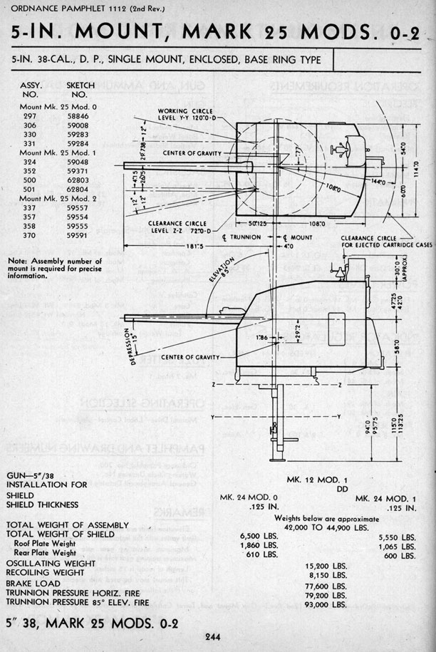
- ^The Mark 25 was the prototype enclosed base ring mounting. Externally, the gun shield was slightly different from the later Mark 30 enclosed mounting, being more rectangular in shape while the Mark 30 was tapered. See mounting photographs and sketches below. As best as I have been able to determine, the Mark 25 was only used for the bow mounts on the four destroyers of the Gridley (DD-380) class, the eight destroyers of the Bagley (DD-386) class and on USS Dunlap (DD-384) and USS Fanning (DD-385). Some of these Mark 25 mounts may have been replaced with Mark 30 enclosed base ring mounts during the war as spares were made for at least the Bagley class.
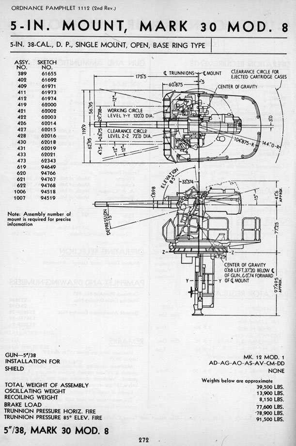
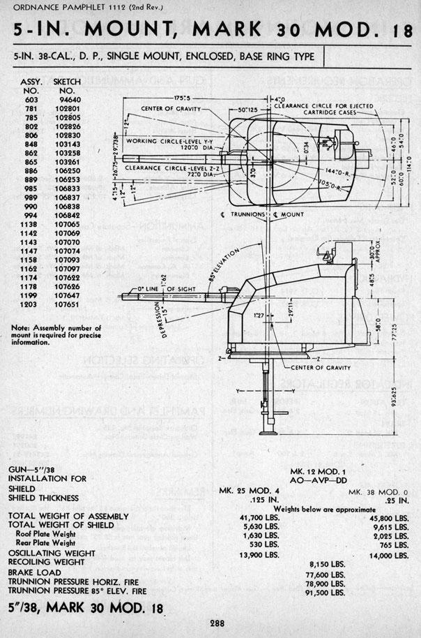
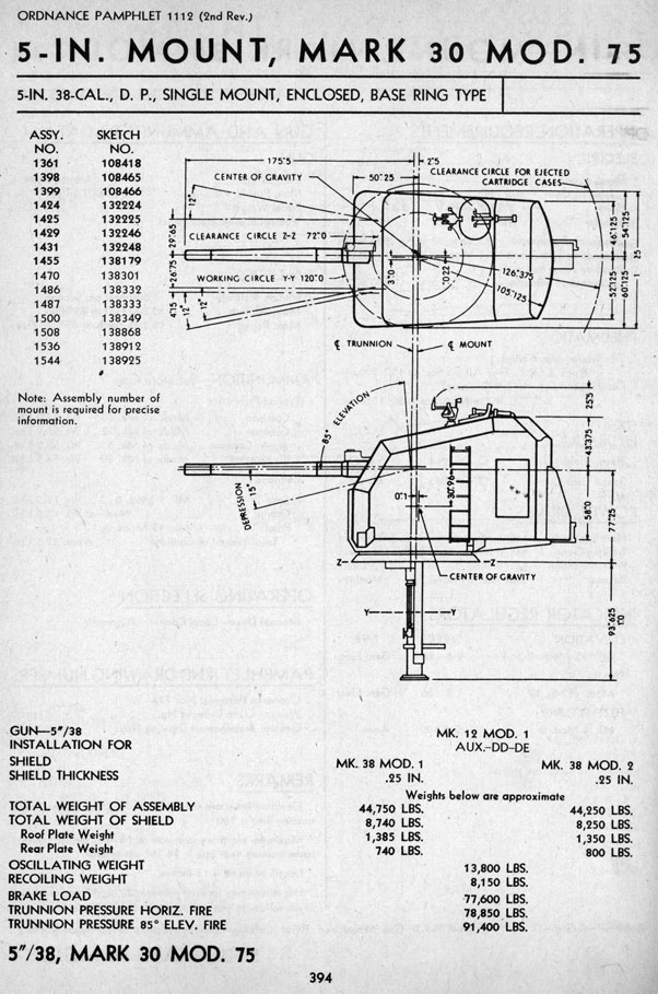
- ^9.19.2Almost all Mark 25 and Mark 30 base ring single mounts had an integral shell hoist on the axis of the mounting which allowed shells to be passed directly to the gun at any angle of train. Fuzes were automatically set as the shells traveled up the hoist. Cartridges were passed up to the gun through a scuttle also on the rotating mass. These base ring mounts with integral shell hoists and cartridge scuttles had the advantage that projectiles and cartridges were presented to the loaders at exactly the same position and orientation regardless of the mount's elevation or train and thus simplified and sped up the loading cycle. Both the shell hoist and the cartridge scuttle were on the left side of the mount. Mark 25 and enclosed Mark 30 base ring mountings used a single 10 hp motor to work both elevation and train, a 7.5 hp motor for the hoists and a 7.5 hp or 5 hp motor for ramming.
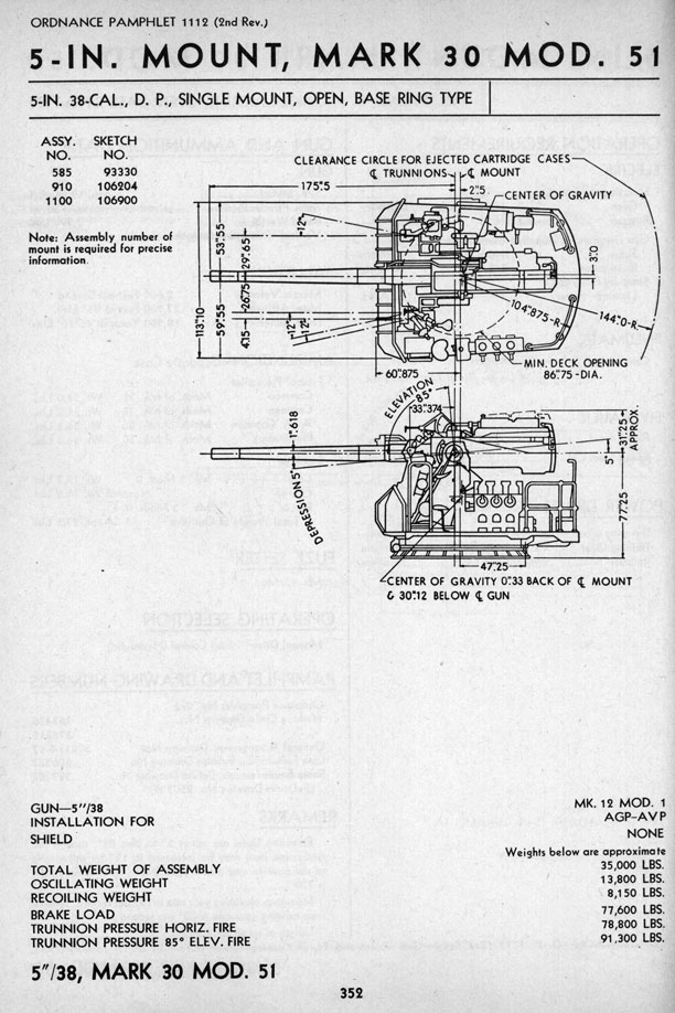
- ^The Mark 30 mountings made up by far the majority of single mountings built during the war. The Mark 30 ran up to Mod 86, with Mod 0 being the original enclosed mounting and Mod 1 being the original open mounting. The Mark 30 Mod 0 enclosed base ring mounts were first introduced on USS Wichita (CA-45). There were also semi-enclosed mounts which had the upper half of the shield removed as a weight savings but having a canvas cover to protect the interior of the mount. Many of the Mark 30 modifications were trivial in nature. For example, USS Fletcher (DD-445) used Mod 16 in positions 1 and 5, Mod 19 in position 2, Mod 30 in position 3 and Mod 31 in position 4. The differences were mainly related to the elevation and training limitations inherent in the different mounting positions. Escort Carriers (CVE) completed during the war used Mark 30 Mod 80 which was a simplified base ring mounting which lacked shields, axial hoists and RPC. The maximum elevation of this Mod was restricted to +27 degrees as it was installed under the flight deck overhang. The single open Mark 30 Mod 48 and Mark 30 Mod 51 mountings were simplified base-ring types for auxiliaries and merchant ships. This Mod lacked integral shell hoists. Mark 30 Mod 50 was another simplified Mod for merchant ships and was apparently so different from the rest of the Mark 30 family that it needed its own ordnance pamphlet, BuOrd OP No. 895. Trunnion height for all Mark 30 Mods was 58.0 inches (147 cm) above the loading platform. 55 inches (140 cm) is considered the maximum desirable trunnion height when firing at low elevations for a 50 - 55 lbs. (22.7 - 24.9 kg) projectile.
- ^The Rudderdow (DE-224) and John C. Butler (DE-339) classes had the top rear of the shield of their bow 5"/38 (12.7 cm) mounting cut off at an angle to allow clearance for the Hedgehog emplacement located directly behind it. See sketch below.
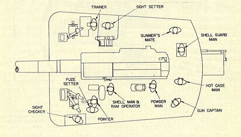
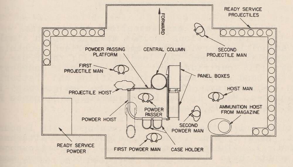
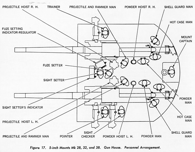
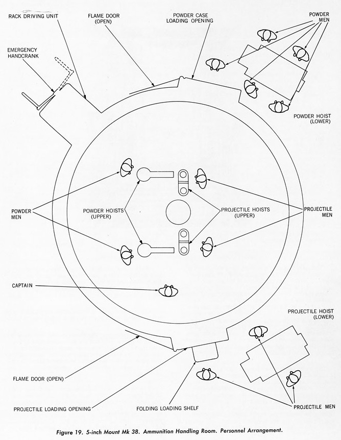
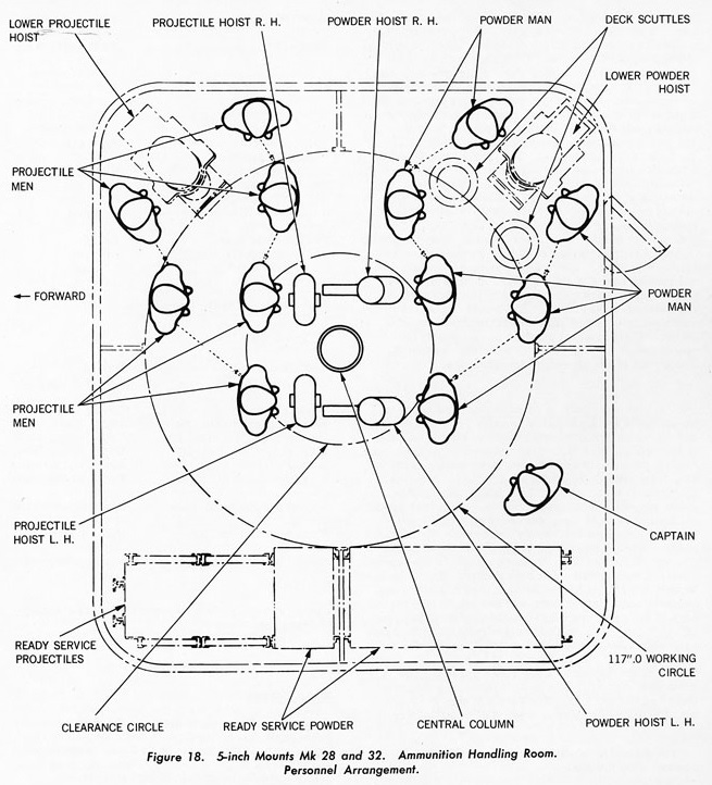
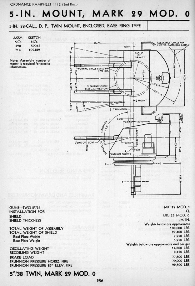
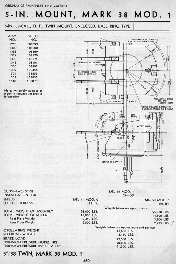
- ^All twin SP and DP mounts were base ring types and were generally similar to single enclosed base ring mounts. Twin mounts differed from single mounts in that there were twin powder hoists for the cartridges on the rotating structure as well as twin shell hoists. The hoists for the right gun came up through the deck on the left side of the gun while those for the left gun came up on the right side of the gun. See diagrams below for crew positions.
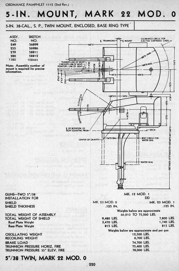
- ^The Mark 22 twin mount used on the Porter (DD-356) and Somers (DD-381) destroyer classes was the only SP mounting ever developed for these weapons. Their low maximum elevation of +35 degrees of elevation was adopted mainly as a weight savings, as it was calculated that these ships would only be able to carry six DP guns rather than the eight SP guns that they actually did carry. The Mark 22 mounting used a 15 hp training motor and a 5 hp elevating motor. Most of the destroyers with these mountings lost their No. 3 mount as weight compensation for growth in other areas and those destroyers modernized during World War II had all of their SP mountings replaced with two twin Mark 38 DP mountings and one single Mark 30 DP mounting.
- ^Most USS Essex (CV-9) class carriers were completed with four Mark 32 twin mounts, mainly Mods 0, 2 and 4, and four Mark 24 Mod 11 single pedestal mounts. Post-war, a few of these ships had their pedestal mounts replaced with Mark 30 base ring open mountings for reasons that are not clear. By the early 1960s, all of the twin mountings had been removed from those carriers still in commission. A few of these carriers were modified by this time such that they now carried eight single mountings, two on each corner. The batteries were reduced during the 1960s, with Essex (CVS-9) carrying four Mark 30 Mod 86 mounts in February 1968, Yorktown (CVS-10) had four Mark 24 Mod 11 mounts as of November 1964, Ticonderoga (CVS-14) had three Mark 24 Mod 11 as of June 1973 and Randolph (CVS-15) carried three Mark 24 Mod 11 and one Mark 24 Mod 6 as of September 1966.
- ^The Mark 38 twin mount used on destroyers was similar in design to the other twin DP mounts but differed by having a much lighter construction and a thinner shield. These mounts also substituted simpler case deflection chutes in place of the more complicated case ejection chutes used on the other Marks to move expended casings off the mount.
- ^The Brazilian Marcilio Dias class were patterned after the USS Mahan (DD-364) class.
- ^The Brazilian Acre class were originally patterned after the British G-H class destroyers, but the use of USN equipment and weapons pushed the design more towards that of the USS Gridley (DD-380) class. The gun in No. 2 position on most of the Acre class was replaced with a twin 40 mm Bofors mounting during refits in the early 1960s.
- ^HMS Delhi replaced her six 6"/45 (15.2 cm) Mark XII guns with five enclosed Mark 30 mounts which were installed in positions 1, 2, 4, 5 and 6. Her forward, midships and after magazines were converted to handle 5" (12.7 cm) ammunition. The magazine formerly used for mount 3 was converted to oil tankerage. Standard US handling rooms were fitted under the mounts, with dredger hoists in each handling room used to bring up ammunition from the magazines below. British fire control equipment was removed and Delhi was given two USN Mark 37 GFCS to control these guns during her refit. Cabling and other electrical and structural work to accommodate British radar equipment was performed in the USA, but no radars were actually fitted until Delhi returned to Britain where Type 285 fire control radars were fitted to the directors.
- ^According to Danish Naval History, these guns when used on the Peder Skram class frigates were designated as 127 mm Gun K M/60 LvSa2. These ships lost one of their Mark 38 mountings in order to fit Harpoon Launchers during the 1980s.
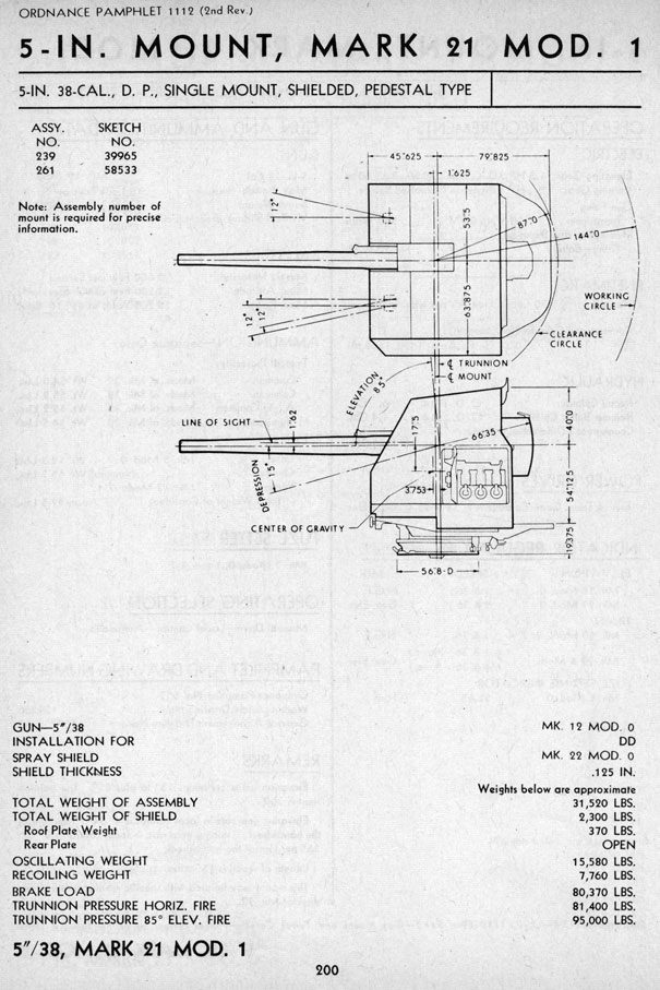
- ^The major differences in weight for enclosed mountings was from the thickness of the shield, which ran from 0.125" (0.32 cm) for destroyer mountings up to 2.5" (6.4 cm) on battleships. The thinness of the shield for destroyer mountings led to water damage, especially on the bow mounting of the A.M. Sumner and Gearing classes. Postwar, many of these destroyers had the front shield on the bow mounting reinforced.
- ^All single and twin DP mounting types were designed to allow +85 degrees of positive elevation, with the exception of those altered for specific applications, such as the Mark 30 Mod 80, which was restricted to +27 degrees to allow installation on escort carriers under the flight deck overhang. Most DP mountings had a maximum negative elevation of -15 degrees, but a few Mods were restricted to -7 or -10 degrees for application reasons.
- ^Ramming was power-worked on all mountings and was either pneumatic or by a 5 hp electric motor with hydraulic drive. This allowed any-angle loading and thus a sustained high rate of fire even at high elevations. In an emergency, guns could be manually rammed but this could not be done when the gun was at high elevations as the projectiles would slide back out. The Gunnery Officer aboard USS Enterprise (CV-6) reported after the Battle of the Eastern Solomons that two of his guns lost power during the battle and that manual ramming reduced their ROF by more than half. However, this same report credits the 5"/38 (12.7 cm) guns on this carrier with three dive bombers definitely shot down and with others set on fire or forced to abort for a total expenditure of only 97 rounds.
- ^The maximum, metal to metal recoil distance was 19 inches (48 cm).
- For enclosed mountings, expended cartridge cases were automatically ejected out the back of the mounting at all elevations up to 35 or 40 degrees. Above that elevation, the shell guard/spademan manually removed the casing from the gun and then the hot-case crewman needed to move the cases from the gun to the ejectors. For open mountings, the cases were allowed to travel freely off the platform deck to the emplacement deck but again at higher elevations the shell guard/spademan and the hot case man needed to remove the expended cases manually.
- All twin DP mountings were equipped with RPC gear and powered by electric motors through hydraulic gear. Training was by a 4 hp motor while the guns were elevated by a 7.5 or 10 hp motor. Each gun had a 7.5 or 10 hp motor for the hoists and a 5 or 7 hp motor for the rammer.
- The Mark 22 SP twin mounting had the gun axes 72 inches (183 cm) apart. All DP twin mountings had the gun axes 84 inches (213 cm) apart.
- The Mark 37 was a much simplified single mounting developed by Northern Ordnance, Inc. that was primarily intended for merchant ships and auxiliaries. This mounting lacked hoists and shields and had a simplified sighting system as it was designed to be used only in local control. Early mods did not have fuze setters but starting with Mod 8 these were added. Over 3,600 were built during the war, with about 1,600 of these being used on merchant ships.
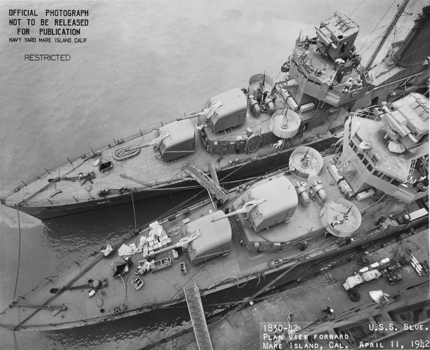
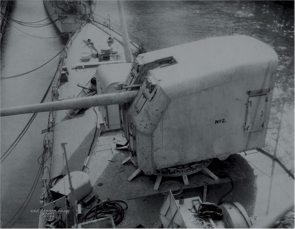
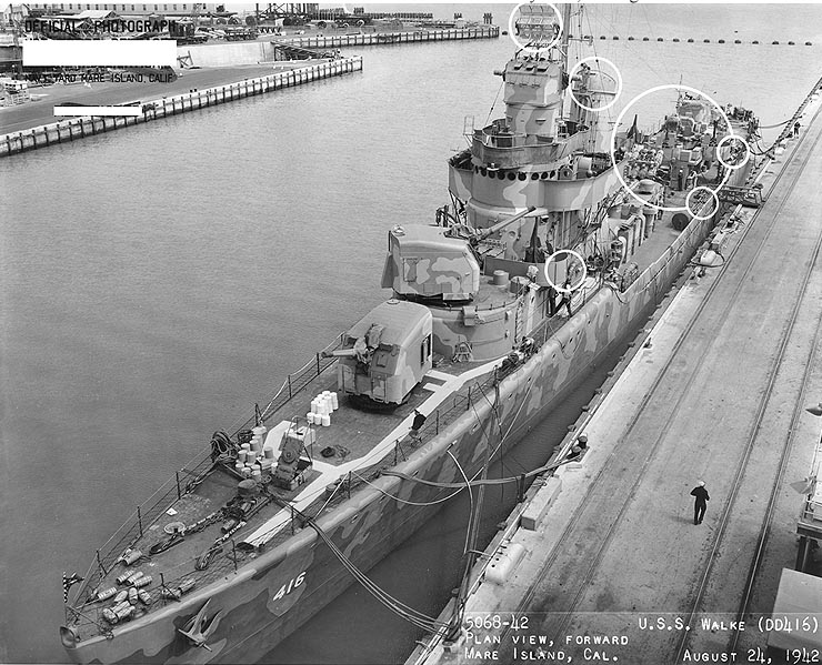
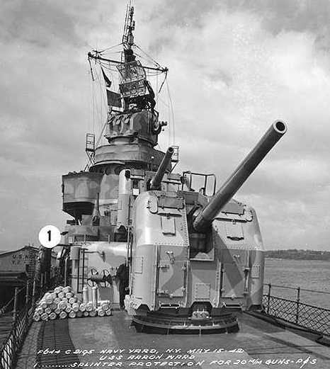
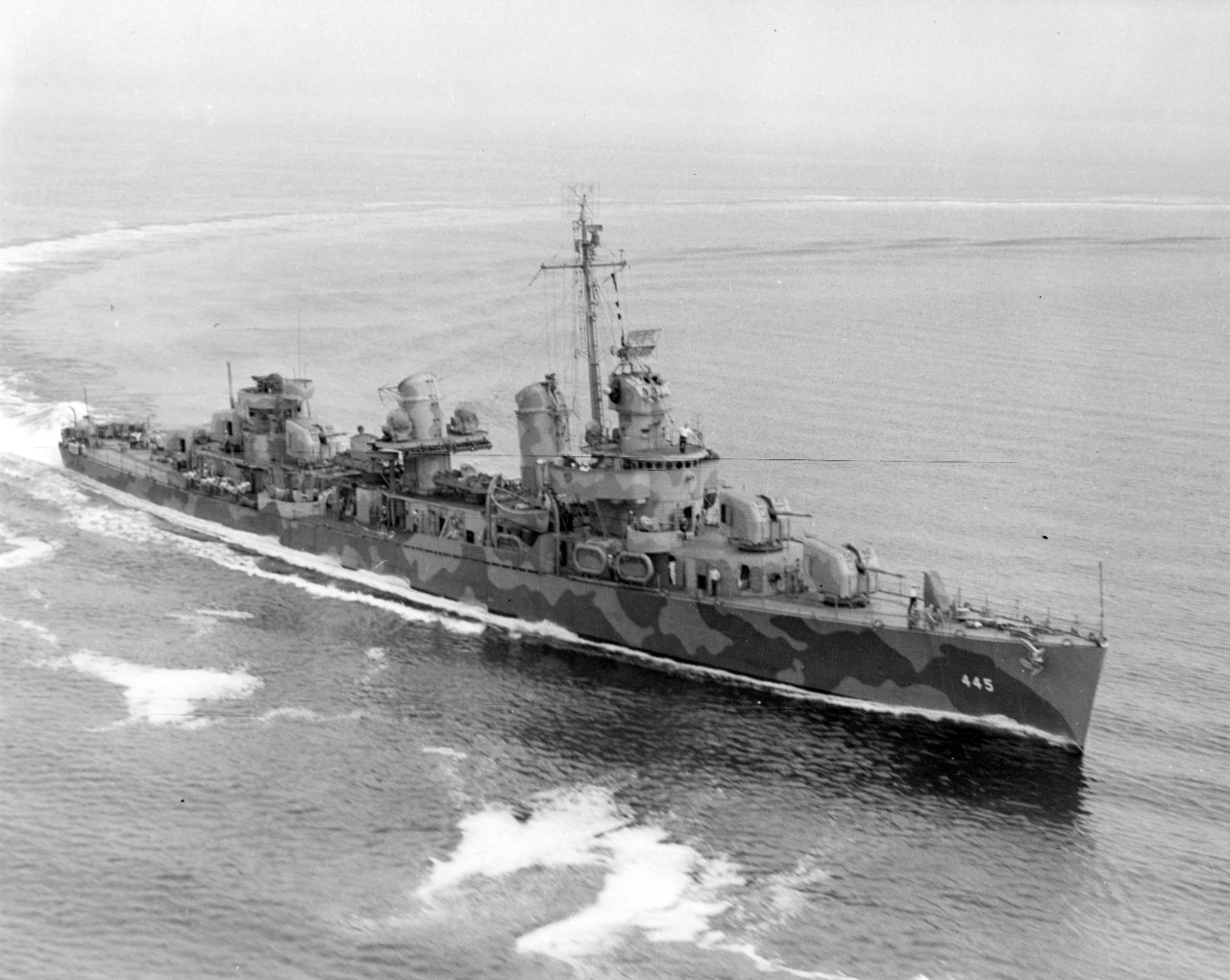
- Destroyers of the Gridley (DD-380), Dunlap (DD-384) and Bagley (DD-386) classes had something of a mixed battery, as they had enclosed base ring mountings on the bow, but open pedestal mountings on the stern. USS Benham (DD-397) was the first destroyer with a uniform battery of base ring single mountings, although the stern mounts were still of the open type. It was not until the larger Fletcher (DD-445) class that destroyers had all of their guns in enclosed mountings.
- Most of the five-gun destroyers built prior to 1942 had mount No. 3 removed during the war as weight compensation for growth in other areas, such as ASW equipment, light AA and electronic installations. Some four-gun destroyers lost one or both gun shields on the stern mountings as weight compensation during the war. The Sims (DD-409), Benson (DD-421) and Gleaves (DD-423) classes started out with three enclosed base-ring mountings (mounts 1, 2 and 5) and two open base-ring mountings (mounts 3 and 4). After experience with an Atlantic winter in 1941-42, the open mounts were replaced with open-top, semi-enclosed versions with a canvas cover for weather protection. Later, as weight compensation, mount 3 was removed from these ships. During her refit in the summer of 1945, USS Shaw (DD-373) was found to be significantly overweight, probably because of the structural strengthening she received during her reconstruction in 1942 to repair damage from the Pearl Harbor attack. As a result, she was reduced to three 5" (12.7 cm) guns in order to allow for additional light AA guns. All of her torpedo tubes were also removed during this refit.
- Some older ships were rearmed with these guns during the war. For example, in 1942 USS Saratoga (CV-3) was rearmed with four 5"/38 (12.7 cm) Mark 32 Mod 2 twin mountings and eight 5"/38 (12.7 cm) Mark 30 Mods 33-36 single mountings. The rebuilt or refitted battleships Nevada (BB-36), Pennsylvania (BB-38), Tennessee (BB-43), California (BB-45), Maryland (BB-46) and West Virginia (BB-48) had their older mixed batteries of 5"/51 (12.7 cm) and 5"/25 (12.7 cm) guns replaced with eight twin 5"/38 (12.7 cm) Mark 32 mountings. USS Idaho (BB-42) had her secondary guns replaced by ten single 5"/38 (12.7 cm) Mark 30 mountings in 1944. After being damaged by a German Fritz X glider-bomb in 1943, USS Savannah (CL-42) had her eight single 5"/25 (12.7 cm) guns replaced with four twin 5"/38 (12.7 cm) Mark 32 mountings. Buckley class Destroyer Escorts DE-217, 218-219, 678-680, 696-698 and 700-701 along with Edsall class Destroyer Escort USS Camp DE-251 had their three 3"/50 (7.62 cm) guns replaced with two 5"/38 (12.7 cm) guns in 1945. From an examination of photographs, I believe that these were Mark 30 Mod 84 for the bow mounts and Mod 85 for the stern mounts.
- A Note on Sources: OP-735 (First Revision - 1943) says that Mark 30 Mod 42 was to be used on Destroyer Escorts, but this does not appear to have been implemented.
- In May 1943 the French proposed that the incomplete battleship Jean Bart be finished in a US yard and submitted two designs to the USN for review. The secondary battery in these proposals consisted of fifteen and seventeen 5"/38 (12.7 cm) Mark 32 twin mountings. Additional detail on this proposal can be found on the French 340 mm datapage. Neither of these conversions were carried out and Jean Bart laid incomplete until after the war.
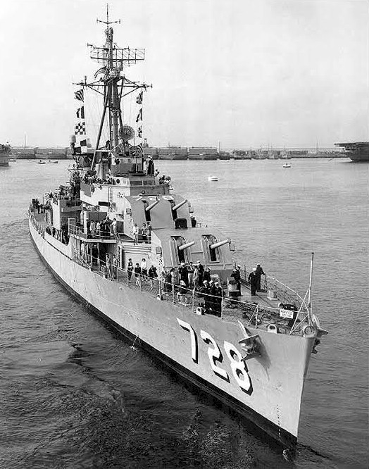
- Post-war, many of the Fletcher, A.M. Sumner and Gearing classes retained in commission lost one of their bow 5"/38 (12.7 cm) mountings in order to install Hedgehog or Weapon Able/Alpha ASW mountings in its place. In addition, most of the Fletcher class destroyers retained in commission lost their amidships 5"/38 (12.7 cm) mounting as weight compensation for additional electronics and many of this class, including USS Fletcher (DD-445) herself, lost one of their stern mountings. leaving them with only two 5"/38 (12.7 cm) guns. Also notable was USS Gyatt (DDG-1, ex-DD-712), a Gearing (DD-710) class destroyer which traded her stern 5"/38 (12.7 cm) mounting for a twin Terrier missile launcher. In contrast, USS Carpenter (DDK-825) was originally commissioned in 1949 with two twin 3"/50 (7.62 cm) mountings but then was rearmed during the early 1950s with two twin 3"/70 (7.62 cm) mountings. She finished out her career in the 1960s with a single twin 5"/38 (12.7 cm) Mark 38 mounting on the bow. Many of these destroyers had the front of Mount 51 reinforced post-war to prevent water damage. See photograph below of USS Mansfield (DD-728) for an example.
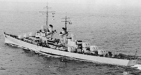
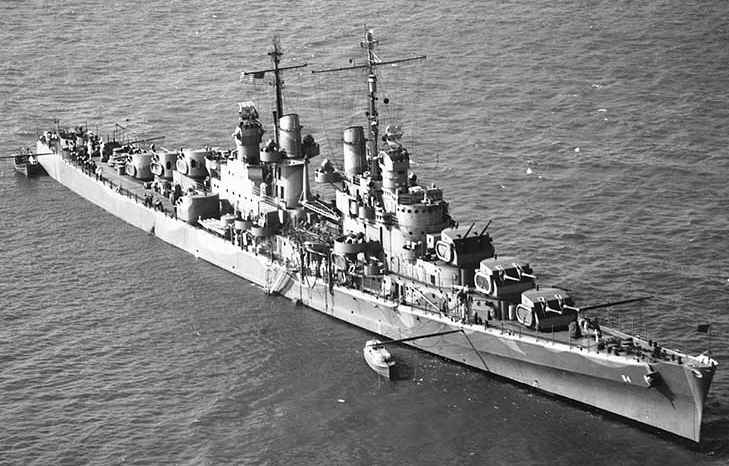
- Six Cleveland class cruisers were converted during the 1950s to Terrier and Talos missile cruisers by having their two 6"/47 (15.2 cm) and three 5"/38 (12.7 cm) stern mountings removed and either a twin Terrier or twin Talos missile launcher installed in their place. Four of these cruisers were further modified into fleet flagships which entailed removal of one of their bow 6"/47 (15.2 cm) mountings and two of their bow 5"/38 (12.7 cm) mountings in order to fit flag and communication spaces. The Baltimore class cruisers USS Boston (CA-69) and USS Canberra (CA-70) had their stern 8"/55 (20.3 cm) mounting and one of their stern 5"/38 (12.7 cm) twin mountings removed in order to fit two twin Terrier launchers during the 1950s.
- Two Baltimore (CA-68) class and one Oregon City (CA-122) class cruisers were heavily modified during the 1950s into all-missile cruisers to become the USS Albany (CG-10) class. These ships had all of their 8"/55 (20.3 cm) and 5"/38 (12.7 cm) mountings removed during their conversions in order to fit two twin Talos and two twin Tartar missile launchers. Later, they had two single 5"/38 (12.7 cm) Mark 30 open mountings added amidships during the early 1960s following a failure to successfully launch missiles during a demonstration. This failure also led to USS Long Beach (CG-9) adding two enclosed 5"/38 (12.7 cm) Mark 30 mountings amidships. All of these added 5"/38 (12.7 cm) gun mountings were of limited use as they had modest fire control installations.
- USS St. Paul (CA-73) had her bow 5"/38 (12.7 cm) mounting removed in the early 1960s in order to fit additional staff accommodations.
- During their modernizations in the early 1980s, the Iowa (BB-61) class battleships had four of their twin 5"/38 (12.7 cm) mountings removed in order to fit Harpoon and Tomahawk missile launchers in their place.
- USCG Hamilton (WHEC-715) was rebuilt starting in 1985 and had her 5"/38 (12.7 cm) gun replaced with a 76 mm (3") Mark 75.
- Armor thickness as given in OP 1112 - Gun Mount and Turret Catalog:
Mark 21 Mod 1: 0.125 in (0.32 cm)
Mark 22 Mod 0: 0.125 in (0.32 cm)
Mark 28 Mod 0: 2.0 in (5.08 cm)
Mark 28 Mod 1: 1.25 in (3.2 cm)
Mark 28 Mod 2: 2.5 in (6.35 cm)
Mark 28 Mod 3: 2.5 in (6.35 cm)
Mark 29 Mod 0: 0.75 in (1.9 cm)
Mark 30 Mod 0: 0.125 in (0.32 cm)
Mark 32 Mod 0: 0.75 in (1.9 cm)
Mark 32 Mod 2: 0.75 in (1.9 cm)
Mark 32 Mod 4: 0.75 in (1.9 cm)
Mark 38 Mod 0: 0.125 in (0.32 cm)Some of these Mods had alternative shield designs of lessor or greater thickness, but the thickness listed above agrees with the ship data that I have for the warships listed in the "Designation" section.
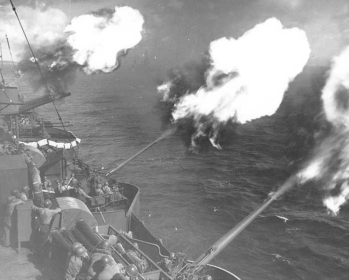
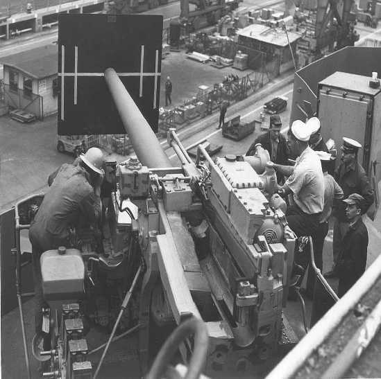
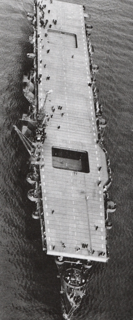
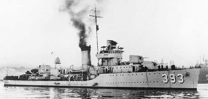
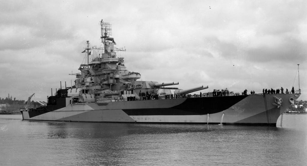
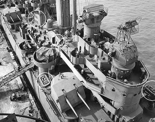
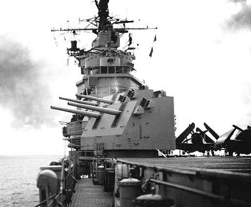
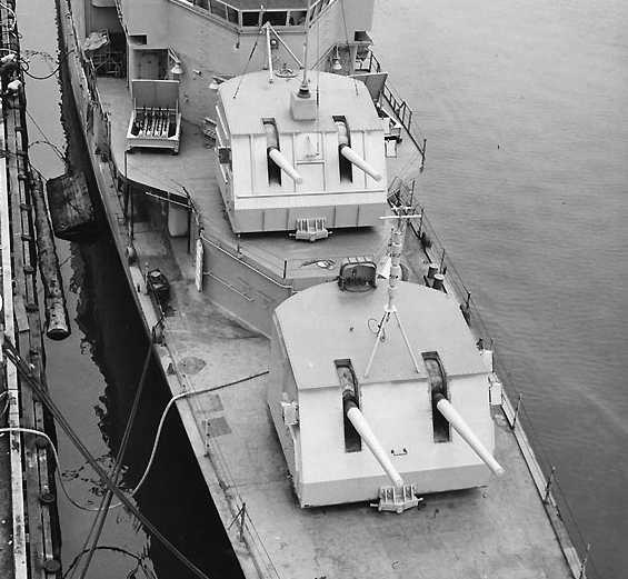
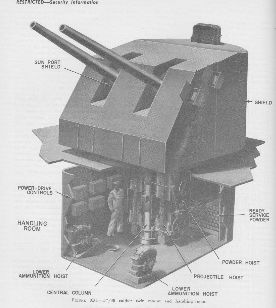
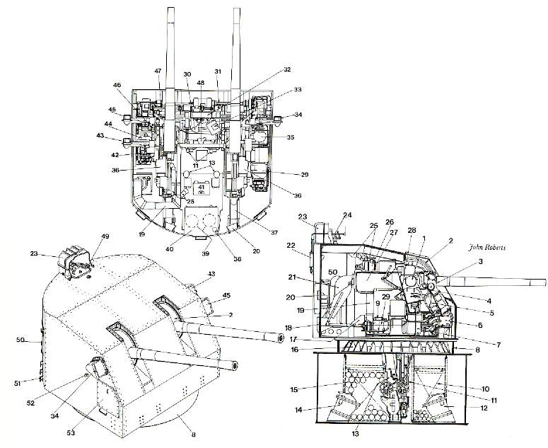
| Description | Description |
|---|---|
| 1. Trunnion | 28. Elevating arc (fixed to gun slide) |
| 2. Gun port shield | 29. Training gear motor |
| 3. Training gear handwheel | 30. Sight-setter's seat |
| 4. Right gun carriage | 31. Training connecting shaft |
| 5. Training indicator regulator | 32. Sight-setter's indicator |
| 6. Training gear box, B-end | 33. Fuze-setting indicator regulator |
| 7. Training gear box, A-end | 34. Trainer's Telescope |
| 8. Barbette (fixed to ship) | 35. Trainer's seat |
| 9. Ventilating system motor | 36. Rammer pump |
| 10. Ready-service projectile stowage in handling room | 37. Case ejector chute |
| 11. Projectile hoist (mount) | 38. Voice tube |
| 12. Projectile hoist (ship) | 39. Ammunition hoist motors, under captain's platform |
| 13. Powder hoist (mount) | 40. Mount captain's platform |
| 14. Powder hoist (ship) | 41. Hatch |
| 15. Ready-service powder stowage in handling room | 42. Elevating gear motor |
| 16. Base ring (training rack on inside) | 43. Checker's telescope |
| 17. Air intake compartment | 44. Pointer's seat |
| 18. Case ejection chute door on back of shield | 45. Pointer's telescope |
| 19. Air vent trunk | 46. Pointer's foot firing pedal |
| 20. Auxiliary case-ejection port, in back of shield | 47. Elevating cross-shaft |
| 21. Case ejector | 48. Fuze-setter's seat |
| 22. Roof hatch counterbalance | 49. Roof hatch |
| 23. Mount captain's blast hood | 50. Rear access door |
| 24. Open sight | 51. Foot rungs |
| 25. Air intakes | 52. Side access door retaining hatch |
| 26. Rammer motor | 53. Side access door |
| 27. Right gun slide |
Photographs by Vladimir Yakubov of 5"/38 (12.7 cm) Mark 12 on USS Hornet (CV-12)
"Naval Weapons of World War Two" and "British Naval Guns 1880-1945 No 14" article in "Warship Volume VIII" both by John Campbell
"Joining the War at Sea 1939 - 1945" by Franklyn E. Dailey Jr., Capt. USNR (Ret.)
"The Naval Institute Guide to World Naval Weapon Systems 1991/92", "US Aircraft Carriers: An Illustrated Design History," "US Battleships: An Illustrated Design History", "US Cruisers:
An Illustrated Design History", "US Destroyers: An Illustrated Design History", "The American 5inch/38 Dual Purpose Gun" article in "Warship Volume II" and "US Naval Weapons" all by Norman Friedman
"Jane's Ammunition Handbook: Ninth Edition 2000-2001" edited by Terry J. Gander and Charles Q. Cutshaw
"Destroyer Weapons of World War 2" by Peter Hodges and Norman Friedman
"Battleships: United States Battleships, 1935-1992" by W.H. Garzke, Jr. and R.O. Dulin, Jr.
"French Battleships: 1922 - 1956" by John Jordan and Robert Dumas
"History of United States Naval Operations in World War II: Volume 14 - Victory in the Pacific" by Samuel Eliot Morison
"U.S. Navy Bureau of Ordnance in World War II" by Lt. Cmdr. Buford Rowland, USNR, and Lt. William B. Boyd, USNR
"US Warships of World War II" by Paul Silverstone
"Little Ship, Big War: The Saga of DE-343" by Edward P. Stafford
"Battleships" by Paul Stillwell
"Iowa Class Battleships" and "Sumner-Gearing-Class Destroyers" both by Robert F. Sumrall
"Destroyers of World War Two" and "Cruisers of World War Two" both by M.J. Whitley
"Nomenclature of USN Aircraft Carrier Gun Mounts" by Christopher C. Wright, a letter published in Warship International No. 2, 1998
---
"Naval Ordnance and Gunnery - Navpers 16116-B - 1952" by Department of Ordnance and Gunnery, U.S. Naval Academy
"Ammunition: Instructions for the Naval Service: Ordnance Pamphlet No. 4 - May 1943" by Bureau of Ordnance (BuOrd), Department of the Navy
"Range Table (Surface Targets) for 5"/38 Cal Gun, 2,600 fsiv - Ordnance Pamphlet No. 551 (First Revision - 2 June 1945)" by Bureau of Ordnance (BuOrd), Department of the Navy
"5-inch Gun Mounts - Pedestal Types - Mark 21 - Ordnance Pamphlet No. 553" by Bureau of Ordnance (BuOrd), Department of the Navy
"5-inch Gun Mounts - Pedestal Types - Mark 24 - Ordnance Pamphlet No. 700" by Bureau of Ordnance (BuOrd), Department of the Navy
"5-inch Gun Mounts - Base Ring Types - Mark 30 and Mark 30 Modifications - Ordnance Pamphlet No. 735 (First Revision - 1943)" by Bureau of Ordnance (BuOrd), Department of the Navy
"5-inch Gun Mounts - Twin Gun Mounts - Mark 29 - Ordnance Pamphlet No. 745" by Bureau of Ordnance (BuOrd), Department of the Navy
"5-inch Gun Mounts - Twin Gun Mounts - Mark 28, 32 and 38 all Mods - Ordnance Pamphlet No. 805" by Bureau of Ordnance (BuOrd), Department of the Navy (online version available at San Francisco Maritime National Park Association)
"U.S. Explosive Ordnance - Ordnance Pamphlet No. 1664 - May 1947" by Bureau of Ordnance (BuOrd), Department of the Navy
"United States Atlantic Fleet, Battleship Division Five, U.S.S. Nevada, BB-36/A16-3/A9 Serial 0060, June 23, 1944" Enclosure A page 23, page 42 of full report
USS Enterprise (CV-6) Gunnery Officer's Action Report for the Battle of the Eastern Solomons
---
"5-Inch Anti-Submarine Projectile EX-30" by R.D. Cromwell, U.S. Naval Proving Ground, Dahlgren, Virginia, Report No. 1044
---
"Operating Instructions for Five Inch, 38 Caliber, Gun Crews" and "OP-1112 - Gun Mount and Turret Catalog" on the HNSA Website
"Ordnance Pamphlet 127: United States Naval Guns, Their Marks and Modifications - April 1942" at Gene Slover's US Navy Pages
---
Special help from Leo Fischer
27 November 2008 - Benchmark
25 January 2009 - Added information on British use
20 September 2009 - Added information for mounts on Hornet (CV-8) in 1942 and on Essex class (CVS-9) post-war
22 December 2009 - Added note on proposed Jean Bart reconstruction
14 January 2011 - Added information on USS Albany (CG-10) and USS Long Beach (CGN-9) mountings, added cutaway sketch
27 February 2011 - Additional information on projectiles, including dyes and Chaff
13 October 2011 - Corrected typographical errors, added Mark 30 trunnion height
02 May 2012 - Added comment regarding USS Carpenter rearmament, added comments regarding missile cruiser conversions
17 October 2012 - Modified Mount / Turret note about HMS Delhi
25 October 2012 - Minor changes for clarity
24 February 2013 - Added rearmament data
05 July 2014 - Added information about crew for Mark 21 mounting and added crew diagram for Mark 21 Mounting
12 January 2016 - Added armor protection, train/elevation rates for Mark 21
03 June 2016 - Converted to HTML 5 format
07 June 2017 - Added note regarding barrel wear during Okinawa campaign
05 July 2017 - Added photograph of USS Independence (CVL-22) and reorganized notes
20 August 2017 - Added photograph of USS Mansfield (DD-728)
20 February 2018 - Reorganized notes
29 September 2018 - Minor formatting changes
12 January 2019 - Added and redid mounting sketches
16 June 2019 - Added notes and sketch regarding those DEs fitted with Hedgehog ASW
31 August 2019 - Minor changes for clarity
09 August 2020 - Added use of Mark 24 mounting, added details and sketch for Mark 25 mounting, added notes regarding blast
hood for mount captain and ejected cartridge cases and added photographs of USS Lamson (DD-367), USS Jarvis (DD-393) and USS Walke (DD-416)
23 October 2020 - Updated to latest template and added sketch of Mark 38 Mod 2 twin mounting
01 December 2020 - Added photograph of USS Farragut (DD-348)
17 October 2021 - Added to Mechanical Fuze Setter Section and to note regarding reduced charges, added photographs of USS Benham (DD-397) and
USS Fletcher (DD-445) and sketch of twin gunhouse
14 June 2022 - Added photograph of loading machine
08 September 2022 - Added comment about CVT fuzes and ammunition outfit for John C. Butler class (DD-339), some changes to the ammunition
outfits for late war destroyers, crewmembers for DP twin mounts, added crew position sketches for twin gunhouse and single and twin handling rooms
01 November 2022 - Changed Yakubov link to point at Wayback Archives
19 December 2022 - Added Trajectory Graph
26 May 2023 - Added links to Battleship Texas (BB-35) and 5"/51 (12.7 cm) gun video
31 August 2023 - Added ammunition outfit for USS Nevada (BB-36) during Normandy operations, revised range table, added photographs of RAP
projectile and casing sectional view
13 September 2023 - Added ammunition stowage for Garcia (FF-1041) and Brooke (FFG-1) classes
02 January 2024 - Fixed broken link to point at Wayback Archives
21 December 2024 - Minor formatting fix
27 February 2025 - Added photographs of USS Selfridge (DD-357) and USS McDougal (DD-358), deleted photograph of USS Phelps (DD-360) and added
note about USS Long Beach (CGN-9)

